Rear Semi-Trailing Arm
The rear semi-trailing arm suspension is an independent rear suspension system similar to the pure trailing arm suspension, with the primary difference being that the bushing axis (or instant axis) runs at an angle in all X, Y, and Z directions. The rear semi-trailing arm suspension combines the advantages of the trailing arm and double-pivot swing axle suspension principles, without the associated disadvantages. The semi-trailing arms resemble triangulated wishbones, with the pivots arranged at an angle to the vehicle's transverse axis and either horizontal or slightly towards the vehicle's centerline.
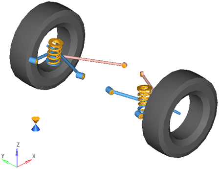
Figure 1. Rear Semi-Trailing Arm Suspension
Model Use
- The wheel body represents the mass and inertia of the tire and the rim.
- The wheel hub body represents the mass and inertia of other rotating bodies such as a brake rotor, but not the half-shafts if the suspension is driven. The wheel hub and brake rotor have no associated graphics.
- The wheel and wheel hub parts use the Wheel CG location as the center of gravity.
- Each body’s Center of Gravity (CG) is estimated from the body’s geometry. The formulas are coded into the point panel and can be seen via the graphical user interface. If more accurate CG locations are available they should be used.
- A wide variety of combinations of suspensions and subsystems can be built using the
Assembly Wizard. You are encouraged to build systems and
understand the resulting model using the graphical user interface.
When building a new suspension model, build the model with all of the optional systems (stabilizer bar, etc) included in the model. Immediately turn off the systems using the Project Browser and run an analysis on the base suspension to ensure it solves properly. As data becomes available for the optional systems; activate those systems and populate them with data.
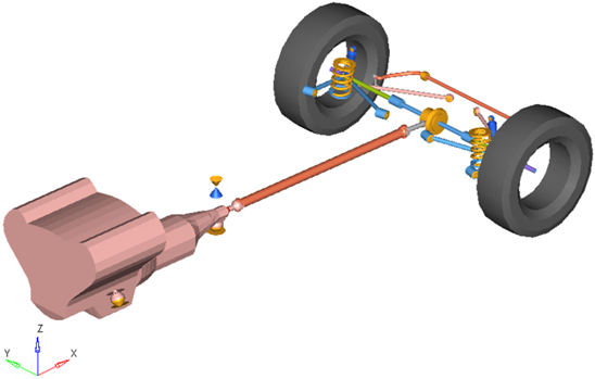
Figure 2. Rear-Half-Vehicle Model Employing a Semi-Trailing Arm Suspension

Figure 3. Browser View of a Rear-Half-Vehicle Model Systems and Subsystems Employing a Semi-Trailing Arm Suspension
Attachments
| Entity | Attaches To |
|---|---|
| Trailing arm, upper link, lower link | Default: Sub-frame No subframe: Vehicle body No vehicle body: Ground |
Points
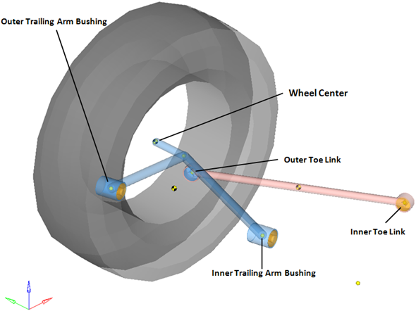
Figure 4. Right Side Principal Points – Rear Semi-Trailing Arm Suspension
Bodies
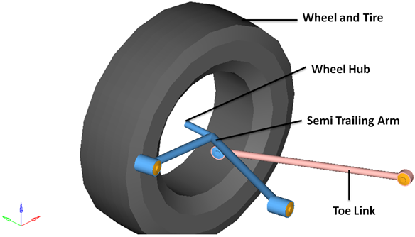
Figure 5. Right Side Bodies – Rear Quad-link Suspension
- The wheel hub body has no associated graphics and therefore is not visible in the image above.
- Optional subsystems may add bodies to the suspension, for example the shock absorber adds two bodies: a shock rod and shock tube. Any bodies added by optional subsystems have been omitted from the image above for clarity.
Bushings and Joints
| Label | Type | Body 1 | Body 2 | Point |
|---|---|---|---|---|
| Trailing Arm Wheel Revolute Joint | Revolute | Wheel Hub | Semi-Trailing Arm | Wheel Center |
| Wheel Hub Fix Jt |
Fixed | Wheel | Wheel Hub | Wheel Center |
| Inner Toe Link Bush | Universal | Toe Link | Semi-Trailing Arm | Inner Toe Link |
| Outer Toe Link Bush | Ball | Toe Link | Semi-Trailing Arm | Outer Toe Link |
| Trailing Arm Outer Bush | Bush | Semi-Trailing Arm | Vehicle Body | Outer Trail Arm Bushing |
| Trailing Arm Inner Bush | Bush | Semi-Trailing Arm | Vehicle Body | Inner Trail Arm Bushing |
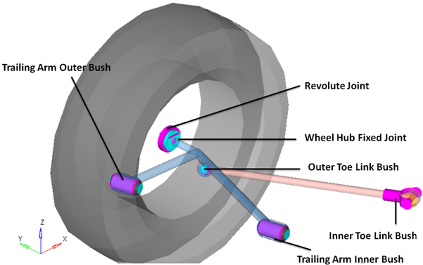
Figure 6. Right Side Joints and Bushings: Rear Semi-Trailing Arm Suspension