Rear Multi-link (with LCA)
The rear multi-link (with LCA) suspension contains three links and a lower control arm, and it is generally used on cars, off-road vehicles, and light trucks. The rear multi-link (with LCA) suspension differs from the conventional rear multi-link suspension in that the two lower links are replaced with a single lower control arm. This suspension offers good load bearing capability due to the single lower control arm, and the two upper links offer flexibility in packaging and suspension kinematics.
In conventional designs, the coil spring, shock absorber, and jounce bumper act between the lower control arm and chassis. The lower control arm carries most of the vertical load and defines the motion of the lower ball joint location on the knuckle, while the three links carry less load and define the kinematics of the suspension.
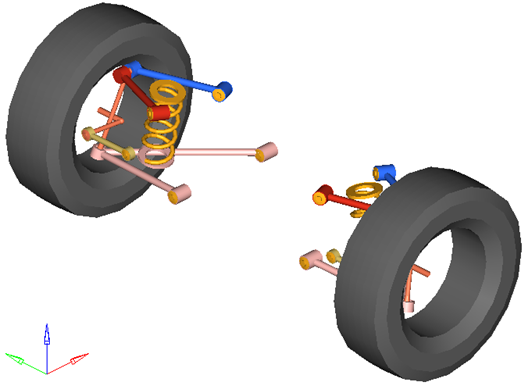
Figure 1. Rear Multi-link (with LCA) SuspensionModel Use
- The wheel body represents the mass and inertia of the tire and the rim.
- The wheel hub body represents the mass and inertia of other rotating bodies such as a brake rotor, but not the half-shafts if the suspension is driven. The wheel hub and brake rotor have no associated graphics.
- The wheel and wheel hub parts use the Wheel CG location as the center of gravity.
- Each body’s Center of Gravity (CG) is estimated from the body’s geometry. The formulas are coded into the point panel and can be seen via the graphical user interface. If more accurate CG locations are available they should be used.
- A wide variety of combinations of suspensions and subsystems can be built using the
Assembly Wizard. You are encouraged to build systems and
understand the resulting model using the graphical user interface.
When building a new suspension model, build the model with all of the optional systems (stabilizer bar, etc) included in the model. Immediately turn off the systems using the Project Browser and run an analysis on the base suspension to ensure it solves properly. As data becomes available for the optional systems; activate those systems and populate them with data.
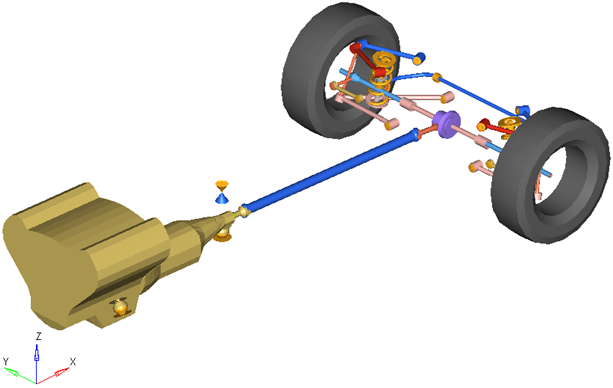
Figure 2. Rear-Half-Vehicle Model Employing a Multi-link (with LCA) Suspension
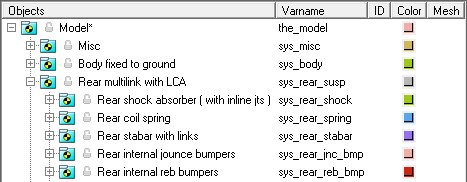
Figure 3. Browser view of a Rear-Half-Vehicle Model Systems and Subsystems Employing a Multi-link (with LCA) Suspension
Attachments
| Entity | Attaches To |
|---|---|
| Front and Rear Lower Control Arm | Default: Sub-frame No subframe: Vehicle body No vehicle body: Ground |
| Front and Rear Upper Control Arm | Default: Vehicle body No vehicle body: Ground |
| Toe Link | Default: Rear sub-frame No rear sub-frame: Vehicle body No vehicle body: Ground |
Points
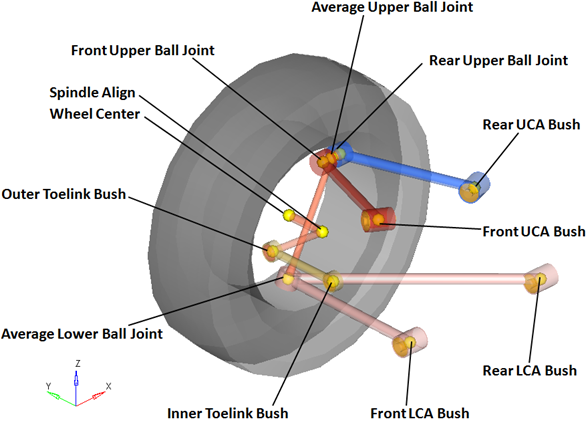
Figure 4. Right Side Principal Points – Rear Multi-link (with LCA) Suspension
Bodies
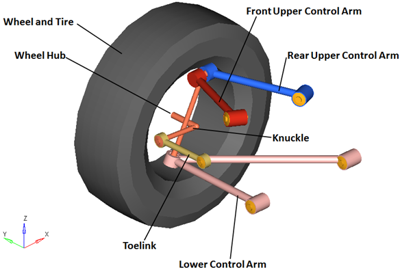
Figure 5. Right Side Bodies – Rear Multi-link (with LCA) Suspension
- The wheel hub body has no associated graphics and therefore is not visible in the image above.
- Optional subsystems may add bodies to the suspension, for example the shock absorber adds two bodies: a shock rod and shock tube. Any bodies added by optional subsystems have been omitted from the image above for clarity.
Bushings and Joints
| Label | Type | Body 1 | Body 2 | Point | Notes |
|---|---|---|---|---|---|
| Lower Ball Joint | Spherical | Knuckle | Lower Control Arm | Average Lower Ball Joint | |
| Front Upper Ball Joint | Spherical | Knuckle | Front Upper Control Arm | Front Upper Ball Joint | When the Compliant option is set to No, the compliance for this joint is turned "Off" and behaves as a pure spherical joint. |
| Front Upper Ball Joint | Spherical | Knuckle | Front Upper Control Arm | Front Upper Ball Joint | When the Compliant option is set to No, the compliance for this joint is turned "Off" and behaves as a pure spherical joint. |
| Rear Upper Ball Joint | Spherical | Knuckle | Rear Upper Control Arm | Rear Upper Ball Joint | When the Compliant option is set to No, the compliance for this joint is turned "Off" and behaves as a pure spherical joint. |
| Wheel Spindle | Revolute | Wheel Hub | Knuckle | Wheel Center | |
| Wheel Hub Fix Jt |
Fixed Joint | Wheel | Wheel Hub | Wheel Center | When the Spindle compliance option is set to Yes, the joint type changes to universal. |
| LCA Front Bush | Bushing | Lower Control Arm | Subframe, Vehicle Body or Ground | Front Lower Control Arm Bush | When the Compliant option is set to No, this bushing becomes a revolute joint. |
| LCA Rear Bush | Bushing | Lower Control Arm | Subframe, Vehicle Body or Ground | Rear Lower Control Arm Bush | When the Compliant option is set to No, this bushing becomes a revolute joint. |
| UCA Front Bush | Universal | Front Upper Control Arm | Subframe, Vehicle Body or Ground | Front Upper Control Arm Bush | When the Compliant option is set to No, this joint compliance is turned "Off" and behaves as a pure universal joint. |
| UCA Rear Bush | Universal | Rear Upper Control Arm | Subframe, Vehicle Body or Ground | Rear Upper Control Arm Bush | When the Compliant option is set to No, this joint compliance is turned "Off" and behaves as a pure universal joint. |
| Outer Toe Link Bush | Spherical | Toe Link | Knuckle | Outer Toe Link Bush | When the Compliant option is set to No, the compliance for this joint is turned "Off" and behaves as a pure spherical joint. |
| Inner Toe Link Bush | Spherical | Toe Link | Subframe, Vehicle Body or Ground | Inner Toe Link Bush | When the Compliant option is set to No, this joint compliance is turned "Off" and behaves as a pure universal joint. |
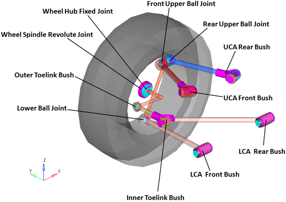
Figure 6. Right Side Joints and Bushings: Rear Multi-link (with LCA) Suspension
Similar Suspensions
Front SLA (1pc LCA)
Rear SLA (1pc LCA)
Front Multi-Link
Rear Multi-Link
Front Multi-Link