Symmetry Types
HyperLife Weld Certification supports reflective and non-reflective symmetries.
Reflective Symmetries
Reflective symmetries link handles in a symmetric fashion so that the movements of one handle will be reflected and applied to the symmetric handles. You can also use reflective symmetries to reflect morphs performed on domains when using the alter dimensions: radius, curvature, and arc angle tools or any map to geom operation. To turn the reflection of morphing operations off, clear the symlinks checkbox or inactivate the symmetry in the Morph Options panel.
- Unilateral symmetries
- Have only one side that governs the others, but not vice versa. For example, handles created and morphs applied to handles on the positive side of the symmetry are reflected onto the other side or sides of the symmetry, but handles created or morphs applied to handles on the other side or sides of the symmetry are not reflected.
- multilateral symmetries
- All sides govern all other sides. For example, a handle created or a morph applied to a handle on any side is reflected to all the other sides.
- Approximate symmetries
- May contain handles that are not symmetric to other handles. For example, handles created on any side of the symmetry are not reflected to the other sides. This option is best for asymmetrical, but similar, domains or for a cyclical symmetry applied to a mesh that sweeps through an arc but not a full circle.
- Enforced symmetries
- Cannot contain handles that are not symmetric on all other sides. For example, handles created or deleted on any side of the symmetry are created or deleted on the other sides so that the symmetry is maintained. When a reflective symmetry is created with the enforced option, additional handles may also be created to meet the enforcement requirements.
- One Plane
- A mirror is placed at the origin perpendicular to the selected axis (default = x-axis).
- In Figure 1, the mesh on the left is before morphing;
the mesh on the right is after morphing. The icon for 1-plane symmetry
is a rectangle perpendicular to the symmetry system's selected axis. You
can think of this rectangle as a mirror. The highlighted handle is
moved. Notice how only the handle at the lower left has been selected
and how the handle on the upper left is automatically moved
symmetrically. This type of symmetry is very useful for a wide variety
of symmetric models.
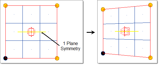
Figure 1. - Two Plane
- Two mirrors are placed at the origin perpendicular to the selected axis and the subsequent axis (that is x and y, y and z, z and x) (default = x and y-axis).
- In Figure 2, the mesh on the left is before morphing; the mesh on
the right is after morphing. The icon for 2-plane symmetry is two
rectangles perpendicular to the symmetry system's selected axis and
subsequent axis. You can think of these rectangles as mirrors. The
highlighted handle is moved. Notice how only the handle at the lower
left has been selected and how the other three symmetric handles are
automatically moved symmetrically. This type of symmetry is very useful
for objects symmetric across two perpendicular planes.
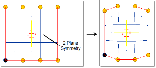
Figure 2. - Three Plane
- Three mirrors are placed at the origin perpendicular to all three axes.
- In Figure 3, the mesh on the left is before morphing; the mesh on
the right is after morphing. The icon for 3-plane symmetry is three
rectangles perpendicular to all three of the symmetry system axes. You
can think of these rectangles as mirrors. The highlighted handle is
moved. Notice how only the handle at the lower right has been selected
and how the other seven symmetric handles are automatically moved
symmetrically. This type of symmetry is very useful for objects
symmetric across three perpendicular planes.
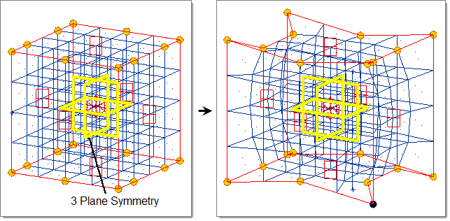
Figure 3. - Cyclical
- Two mirrors are placed along the selected axis (default = z-axis) and run through the origin with a given angle in between that is a factor of 360. The result is a wedge that is reflected a certain number of times about the selected axis.
- Figure 4
is an example of cyclical symmetry with a cyclical frequency of 8 (45
degrees per wedge). The mesh on the left is before morphing and the mesh
on the right is after morphing. The icon for cyclical symmetry is a
number of spheres lying perpendicular the symmetry system's selected
axis and connected to the origin with lines. The number of spheres is
equal to the number of symmetric wedges. Each cyclical wedge is
identical to the others when rotated through an angle (in this case 45
degrees) about the selected axis. The highlighted handle is moved.
Notice how only one handle has been selected and how the other seven
symmetric handles are automatically moved symmetrically. This type of
symmetry is very useful for objects that repeat at regular intervals
about a central point.
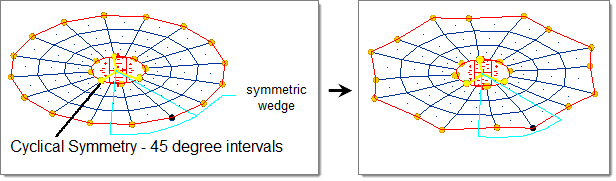
Figure 4.
Non-Reflective Symmetries
Non-reflective symmetries are linear, circular, planar, radial 2D, cylindrical, radial + linear, radial 3D, and spherical. These change the way that handles influence nodes as well as link the symmetric handles so that the movement of one affects the others. You can control whether or not a handle perturbation is applied to symmetric handles for both reflective and non-reflective symmetries by selecting or clearing symlinks or making the symmetries active or inactive in the Morph Options panel. However, the unique handle to node influences for non-reflective symmetries can only be turned off by making the symmetry inactive.
- Linear
- Handle acts as a line drawn through the handle location parallel to the selected axis (default = x-axis).
- In Figure 5, the mesh on the left is before morphing; the mesh on
the right is after morphing. The icon for linear symmetry is two
parallel lines extending along the selected axis. The highlighted handle
is moved. Notice how the handles act on the mesh as if they were
parallel lines. This type of symmetry is very useful for changing the
shape of entire cross-sections by moving only a few handles.
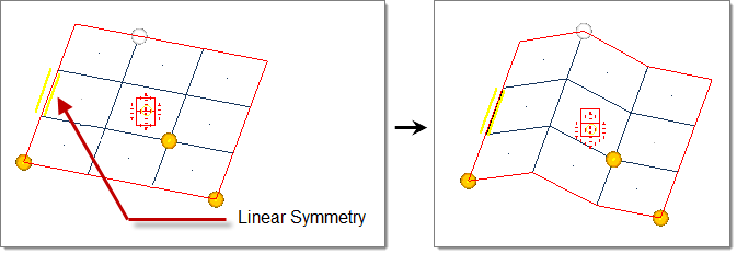
Figure 5. - Circular
- Handle acts as a circle drawn through the handle position about the selected axis (default = z-axis).
- In Figure 6, the mesh on the left is before morphing; the mesh on
the right is after morphing. The icon for circular symmetry is a circle
at the origin of the symmetry system lying perpendicular to the selected
axis. The highlighted handle is moved. Notice how the handles act on the
mesh as if they are circles about the selected axis. This type of
symmetry is very useful for keeping a circular part circular while
manipulating its shape.
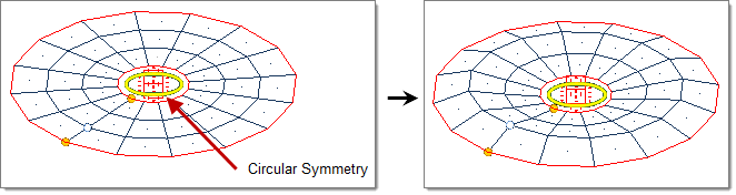
Figure 6. - Planar
- Handle acts as a plane drawn through the handle location perpendicular to the selected axis (default = x-axis).
- In Figure 7, the mesh on the left is before morphing; the mesh on
the right is after morphing. The icon for planar symmetry is a shaded
rectangle perpendicular to the symmetry system's selected axis. The
highlighted handle is moved. Notice how the handles act on the mesh as
if they were perpendicular planes. This type of symmetry is very useful
for manipulating the shape of regular sections along their length
without changing their profile.
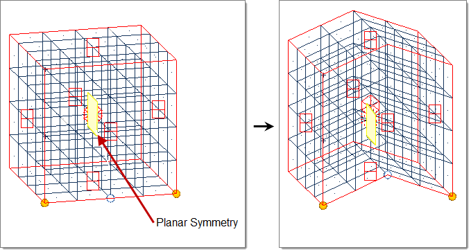
Figure 7. - Radial 2D
- Handle acts as a ray drawn through the handle position originating from and extending perpendicular to the selected axis (default = z-axis).
- In Figure 8, the mesh on the left is before morphing; the mesh on
the right is after morphing. The icon for radial 2-D symmetry is a flat
cone with its vertex at the symmetry system origin and perpendicular to
the selected axis. The highlighted handle is moved. Notice how the
handles act on the mesh as if they were rays extending in a radial
direction away from the selected axis. This type of symmetry is very
useful for changing the shape of a part while keeping its radial profile
intact.
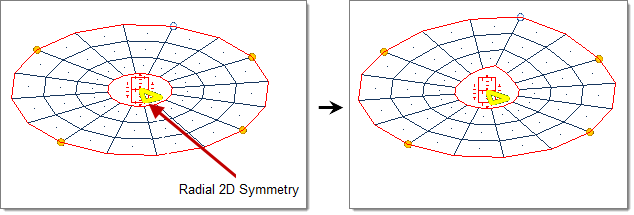
Figure 8. - Cylindrical
- Handle acts as a cylinder drawn through the handle position about the selected axis (default = z-axis).
- In Figure 9, the mesh on the left is before morphing; the mesh on
the right is after morphing. The icon for cylindrical symmetry is a
cylinder parallel to the symmetry system's selected axis centered about
the origin. The highlighted handle is moved. Notice how the handles act
on the mesh as if they were cylinders. This type of symmetry is the
equivalent of using both circular and linear symmetry together and is
very useful for making circular changes to solid meshes.
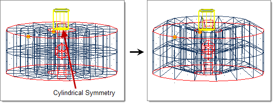
Figure 9. - Radial + Linear
- Handle acts as a plane drawn through the handle position extending from the selected axis (default = z-axis).
- In Figure 10, the mesh on the left is before morphing; the mesh on
the right is after morphing. The icon for radial+linear symmetry is a
3-D wedge lying perpendicular to the selected axis with its vertex at
the symmetry system origin. The highlighted handle is moved. Notice how
the handles act on the mesh as if they were planes parallel to and
extending away from the selected axis. This type of symmetry is the
equivalent of using both radial and linear symmetry together and is very
useful for making radial changes to solid meshes.
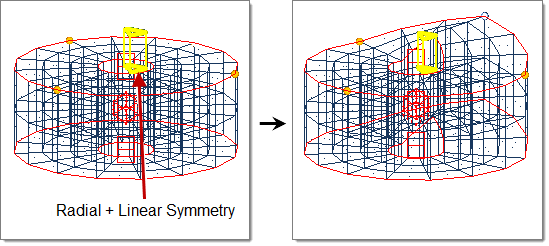
Figure 10. - Radial 3D
- Handle acts as a ray drawn through the handle position originating from origin.
- Figure 11
is an example of radial 3-D symmetry. The model is a hollow sphere made
with solid elements. The mesh on the left is before morphing; the mesh
on the right is after morphing. The icon for radial 3-D symmetry is a
cone with its vertex at the origin of the symmetry system. The
highlighted handle is moved. Notice how the handles act on the mesh as
if they were rays extending away from the origin. This type of symmetry
is very useful for making radial changes to spherical objects.
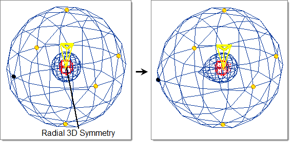
Figure 11. - Spherical
- Handle acts as a sphere drawn through the handle position centered on the origin.
- In Figure 12, the mesh on the left is before morphing; the mesh on
the right is after morphing. The model is a hollow sphere made with
solid elements. The icon for spherical symmetry is a sphere centered at
the symmetry system origin. The highlighted handle is moved. Note how
the handles act on the mesh as if they were spheres centered at the
origin. This type of symmetry is useful for changing the shape of
spherical objects while keeping their spherical shape intact.
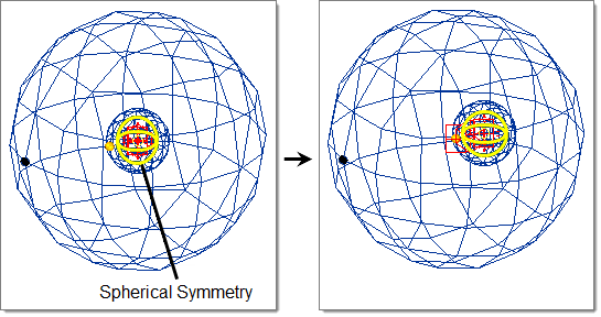
Figure 12.