Pressures Panel
Use the Pressures panel to create pressure loads on elements by applying a load, representing pressures, to a 1D or 2D element, or to the face of a solid element.
Location: Analysis page
For most solvers, the pressure load is considered as force/area, therefore the magnitude of the pressure is multiplied by the calculated area of the elements to which it is applied and resolved as concentrated force loads at the associated nodes.
Pressures are load config 4 and are displayed as a vector with the letter P at the tail end.
Create Subpanel
Use the Create subpanel to create new pressures. You can specify the pressure's footprint by selecting the elements it affects, as well as its direction, magnitude, and the size in which its visual indicators are drawn. You can also apply the pressure to the faces of solid elements, or to the edges of plate elements.
| Option | Action |
|---|---|
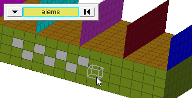
| elems selector | Select elements (1D,
2D, 3D) to which pressures will be applied. Use the switch to
change the selection mode.
Note: If you leave the Pressures panel,
your current selection will disappear, but it will be
restored once you return to the panel.
Changing the selection mode will clear your current selection. Use the Entity Editor to select elements using multiple selection modes. |
| magnitude = |
|
| normal / N1,N2,N3 |
|
| relative size / uniform size |
Note: This setting does not affect the pressure load, only the
length of its graphical indicators.
|
| label loads | Display text labels for each of the loads in the modeling window. |
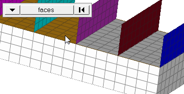
| nodes on face / nodes on edge |
Note: Available when the selector is set to entities.
|
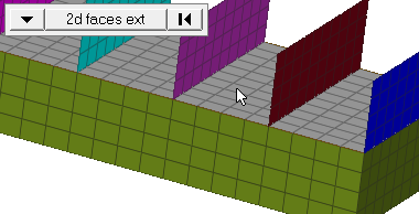
| face angle / individual selection |
|
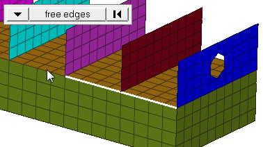
| edge angle |
Split edges that belong to a given face. When the edge
angle is 180 degrees, edges are the continuous boundaries of faces. For smaller
values, these same boundary edges are split wherever the angle between segments
exceeds the specified value. A segment is the edge of a single element.
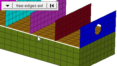
Important: Only available when the entity selector is set to nodes and the
selection mode is set to free edges, free edges ext, edges, or edges
ext.
|
| load types = | Select a load type to apply to the pressure. |
Update Subpanel
| Option | Action |
|---|---|
| loads | Select the existing loads that you wish to modify. |
| display | Display the loads on the model. |
| magnitude = |
|
| normal / N1,N2,N3 |
|
| relative size / uniform size |
Note: This setting does not affect the pressure load, only the
length of its graphical indicators.
|
| label loads | Display text labels for each of the loads in the modeling window. |
| load types = | Select a load type to apply to the pressure. |
Command Buttons
| Button | Action |
|---|---|
| create | Create a new pressure on the selected elements, based on the criteria you have specified. |
| create/edit | Create a new pressure on the selected elements, based on the criteria you have specified, and open a temporary card editor panel based on the specified load type. |
| reject | Undo the most recent create action. |
| update | Change the selected pressure to have the characteristics currently set in the Update subpanel. |
| review | Click review, then select a pressure in the modeling window to display the characteristics for that load (such as magnitude, vector, X/Y/Z/ components, and so on) in the panel fields. |
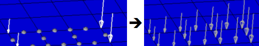
Equations allow you to create force, moment, pressure, temperature or flux loads on your model where the magnitude of the load is a function of the coordinates of the entity to which it is applied. An example of such a load might be an applied temperature whose intensity dissipates as a function of distance from the application point, or a pressure on a container walls due to the level of a fluid inside.
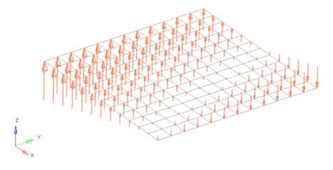
Figure 9. Flat Plate with a Linear Function for an Applied Force Magnitude = 20 – (5*x+2*y). The flat plate is 20 x 20 units, lying in the X-Y plane with the origin at the center.
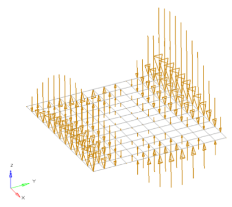
Figure 10. Flat Plate with a Polynomial Function with Magnitude = x^2-2y^2+x*y+x+y. The flat plate is 20 x 20 units, lying in the X-Y plane with the origin at the center.
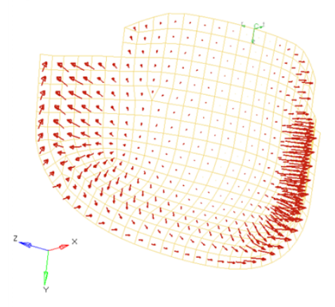
Figure 11. Curved Surface with a Polynomial Function for an Applied Pressure Magnitude = -((x^2+2*y^2+z)/1000). The pressure function is defined in terms of the cylindrical coordinate system displayed at the top edge of the elements.