Surface Edit Panel
Use the Surface Edit panel to perform a variety of surface editing, trimming, and creation functions. This panel also allows you to offset surfaces in their normal direction.
Location: Geom page
Trim with Nodes Subpanel
Use the Trim with Nodes subpanel to trim (split) a surface using nodes. A surface can be trimmed with two or more nodes, or with a node normal to an edge.
For a two nodes trim, select two nodes that belong to a single surface. HyperLife Weld Certification detects the surface that needs to be trimmed. If HyperLife Weld Certification detects more than one unique surface to be trimmed, the trimming operation fails. The surface is trimmed by a projection of the line connecting the two nodes. The projection is performed in the direction normal to the surface.
For a multiple nodes trim, HyperLife Weld Certification creates a smooth line through the nodes selected (these nodes need not be part of the surface that is selected to be trimmed) and then trims the selected surfaces with a projection of this line along the surface normal. These trimming operations can split the surface into multiple surfaces if the line cuts the entire surface.
| Option | Action |
|---|---|
| two nodes: node selector | Select the first and second node on a single surface. The surface operation is performed after you select the second node. |
| multiple nodes: surfs selector | Select the surface to trim. |
| multiple nodes: node list | Select the nodes that define the line you want to use to trim the surfaces. |
| node normal to edge: node selector | Select the node to begin the trim operation. The surface is split along a vector that passes through this node perpendicular to the selected line. |
| node normal to edge: lines selector | Select the line to begin the trim operation. The surface is split along a vector perpendicular to this line that passes through the selected node. |
Trim with Lines Subpanel
- Trim with a cut line
- Drag or draw a line across to define the cut.
- Trim lines
- Sweep existing lines to surfaces, effectively projecting a copy of the selected line to the selected surface and trimming it. For example, this allows you to use a circular line currently offset from the surface to create circular holes in the surface.
- With offset line
- Select existing lines on a surface and create offset or scaled copies of them to trim the surface.
Trimming the selected surface(s) to a line involves sweeping a line along a vector to create a temporary surface, and trimming the selected surface(s) with the temporary surface. You can use the entire surface/distance = toggle to set the distance the line is swept, or use a calculated distance that trims the entire selected surface(s). If the temporary surface does not intersect the selected surface(s), an error is reported. When a surface is trimmed, it is actually broken into smaller pieces (surfaces). After the surface is trimmed, you can delete any unwanted surfaces.
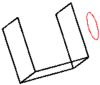 Figure 1. Before Trimming: Surfaces Selected |
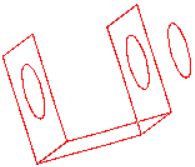 Figure 2. After Trimming: Entire Surface Trimmed with Line |
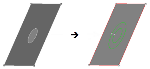
Figure 3. Outer Rectangular Surface and Circular Line Selected
| Option | Action |
|---|---|
| with cut line: surfs selector | Select the surface to trim. |
| drag a cut line | Create a dragged line to cut the surface. A line stretches dynamically between the first point selected, and the current location of the mouse pointer. |
| smooth line | Create a curved line that passes through the points you specify |
| close line | Create a closed loop, automatically connecting the first and last points that you specify. |
| fill cuts | Insert pieces of the trimmer surface into closed loops of new edges. |
| with line: surfs selector | Select the surface to trim. |
| with lines: lines selector | Select the type of
line you want used to trim the surface on your model.
|
| along a vector / normal to surface |
|
| entire surface / distance | Choose between trimming the entire surface, or trimming only a user-specified distance. If you choose to use a specific distance, specify it in the distance = field. |
| vector selector | Select the vector coordinates. |
| keep line endpoints | Retain the line's end points as fixed nodes on the trimmed surface. |
| all attached surfaces / selected surfaces |
|
| offset | Specify the offset. The resulting additional lines will be generated this distance from the selected ones. |
| select closed loops | Automatically select
enclosed chains of line segments when selecting lines. Clear this checkbox to only select the line segments specifically clicked. |
Trim with Surfs/Plane Subpanel
Use the Trim with Surfs/Plane subpanel to trim or split surfaces with another surface or a plane. This function determines the intersection of the selected surfaces and a plane or a surface, and then trims the original surfaces at this intersection.
When surfaces are trimmed, they are broken into smaller pieces (surfaces). After the surfaces are trimmed, you can delete any unwanted surfaces.
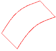 Figure 4. Surface Selected |
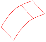 Figure 5. Surface Trimmed |
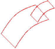 Figure 6. Smaller Surface to be Trimmed |
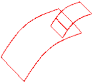 Figure 7. Surface Trimmed |
| Option | Action |
|---|---|
| with plane: surfs selector | Select the surface to
trim. When trim with planes is active, a fill cuts mode is available. This mode is turned off by default. Select fill cuts checkbox to enable it. |
| vector selector | Select the vector coordinates. |
| fill cuts | Insert pieces of the trimmer surface into closed loops of new edges. |
| with surfs: surfs selector | Select the surface to trim. |
| trim both | Enable both surfaces trim each other. |
| extend trimmer | Extend the trimming
operation beyond the boundaries of the nodes, or lines that you
used to define it. Note: Available when trim both is
inactive.
|
| self-intersecting surfs: surfs selector | Select the surface to
trim. Every selected surface is trimmed at their intersections with each other. This is very similar to using the trim both option when trimming with surfs, except that you simply select a single mass of surfaces and HyperLife Weld Certification sorts them all out and trims each one whenever it intersects any other selected surface. This feature is useful when dealing with cases such as a grid of intersecting surfaces. Using the intersecting surfaces trim option allows you to separate all of the intersecting surfaces into multiple smaller surfaces with a single action, instead of having to trim them in pairs. |
Untrim Subpanel
| Option | Action |
|---|---|
| at cursor: edge | Remove a single,
specific trim line.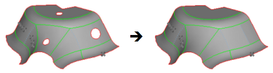 Figure 8. . Clicking each of the circular trim lines (holes) removes the trim and extends the surface. |
| all trim lines of surfs: surfs selector | Remove all of the trim
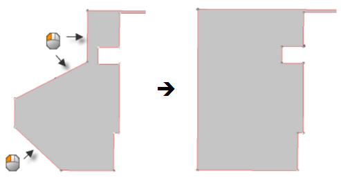
lines on one or more surfaces that are selected. 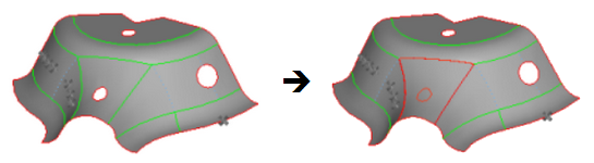 Figure 9. . Selecting the front face surface trims all of its lines, including the one forming the hole in its center. |
| Selected trim lines of surfs: lines | Select trim lines so
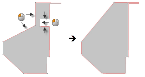
that you can untrim portions of the surface.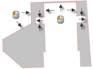 Figure 10. Edges Selected. Arrows indicate selected edges. 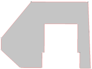 Figure 11. Edges Trimmed . Each selected edge is trimmed. |
| Selected trim lines of surfs: shortcut/ extend | Select a method for
untrimming surfaces.
|
| Selected trim lines of surfs: keep vertices | Keep the points denoting vertices after untrimming. |
| internal trim lines: lines selector | Remove one or more
trim lines inside the boundaries of the surface selected. 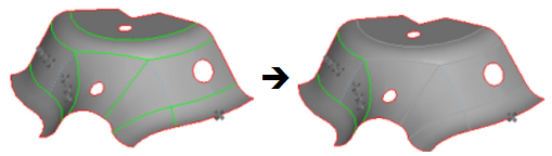 Figure 14. . Clicking each shared edge line removes it, stitching the adjacent surfaces. |
Offset Subpanel
Use the Offset subpanel to offset a group of surfaces by a given distance along the normals of those surfaces. A negative offset value can be used to offset these surfaces in the opposite direction of the surface normal. The topology of the surface edges (free, shared edges, and so on) is maintained during the offset function. Some individual surfaces will be trimmed or extended to maintain the connectivity. This function moves the selected surfaces to the new location.
If you want to save the original surfaces, the selected surfaces can be duplicated before the offset. You can review the normal direction of the surfaces by clicking vector normal or color normal. If the offset direction is incorrect, the reverse normal function can be used to reverse the normal of a selected surface. If there are elements associated to the offset surfaces, the element will not move along with surfaces. The association between the elements and their surfaces is broken.
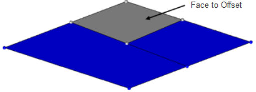
Figure 15. No Offset Performed on Surface
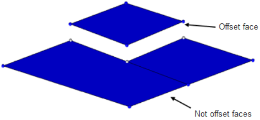
Figure 16. Disjointed Surface
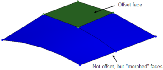
Figure 17. Offset using the Continuous Option
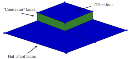
Figure 18. Offset using the Continuous Option, with Separator Lines Specified. Separator lines are specified at the edges of the offset surface.
| Option | Action |
|---|---|
| disjoint offset / continuous offset |
|
| update eccentricity | Specify a value to be stored internally, and can be used later by the Midsurface Thickness Map utility. It will not affect the movement of the offset surface; instead, the surface's associated thickness and offset values will remain in its original location, but be given values relative to its new location. Later, these values can be used in the midsurface thickness utility to map its thickness and offset to FE elements. |
| remove degenerations | Remove degenerations, which are surfaces that become collapsed or unnecessary as a result of the offset. |
| autocomplete separators | Automatically select all segments of a closed loop of lines when you select a single line within the segment. |
| surfs selector | Select the surface to offset. |
| separator lines: lines selector | Select where the offset surface should remain attached; new surfaces will be generated to keep the surface continuous. |
| offset = | Specify a positive or
negative offset value. If you are uncertain where the positive
normal direction lies, use the vector normal or color normal
buttons to display it, and reverse normal if
necessary/desired. Note: The edges of a surface
are offset in the normal direction, so curved surfaces may
expand or shrink when offset in either the positive or
negative direction. Surface dimensions are not
preserved.
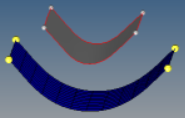 Figure 19. |
Extend Subpanel
Use the Extend subpanel to extend or retract the edges of selected surfaces to meet other selected surfaces, or to close gaps between surfaces or holes within a selected surface.
| Option | Action |
|---|---|
| max extension / extend over edges |
|
| to surfaces | Extend the extending
surfaces as far as necessary to meet these ones. Note: Available
when extend over edges is selected.
|
| by distance / by thickness multiplier |
|
| by filling gaps / by distance / to surfaces |
|
| surfs: to extend selector | Select surfaces to
extend. If you selected any shared (green) or non-manifold (yellow) edges as lines: to extend over, then this selector enables you to specify the corresponding surfaces so that HyperLife Weld Certification knows which surface to use to determine the plane of extension for the shared/non-manifold edge. Additionally, you may need to use this selector to specify any "target" surfaces, particularly if you use the cross extension option. Edges will only extend toward surfaces that are also selected, even if those additional surfaces have no extending edges. These recipient/target surfaces will also be trimmed, if the trim result surfaces checkbox is enabled. |
| cross extension / surfs: to target selector |
|
| lines: to extend over | Select edges to extend. Surfaces will be extended across these lines. If you select a free edge, this also selects and highlights the corresponding surface. |
| surfs: to extend | Select surfaces to extend. |
| surfs: to target / cross extension |
|
| trim result surfaces | When this checkbox is
enabled and all of the selected surfaces are extended or
shortened to have their edges meet, then the selected surfaces
will be trimmed or stitched regardless of which components they
belong to. When this checkbox is cleared, the result varies
further.
When this checkbox is enabled and the selected surfaces extend through their target surfaces, or even merely to the interior without actually touching any of the target surface edges, the surfaces will be both trimmed and stitched at the intersection regardless of whether or not they belong to the same component. However, when this checkbox is cleared, the surfaces are not trimmed or stitched, since they do not meet at any edges. |
Shrink Subpanel
Use the Shrink subpanel to shrink the surface by drawing all of its edges (including internal edges from holes, and so on) back away from their starting location.
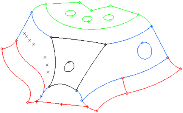
Figure 20. Surface Before Shrinking. The black surface has been selected.
Figure 21. Surface After Shrinking. The edges of the selected surface pull inward, away from the initial edge locations.
| Option | Action |
|---|---|
| surfs selector | Select surfaces to shrink. |
| offset | Specify the distance
that each edge of the surface moves further into the surface.
Note: Holes in the surface will get larger, not
smaller, as their edges move further into the surface
instead of out into the empty space bounded by the
hole.
|