Find Panel
Use the Find panel to locate entities in a database.
Location: Tool page or 1D page > Connectors module
Find Entities Subpanel
Use the Find Entities subpanel to find individual elements in your model.
| Option | Action |
|---|---|
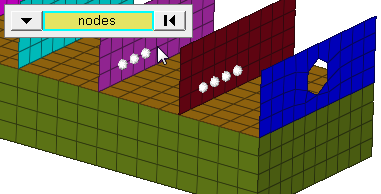
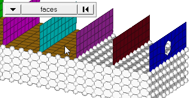
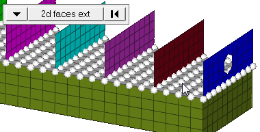
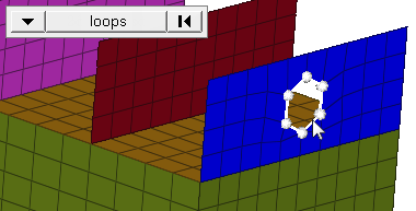
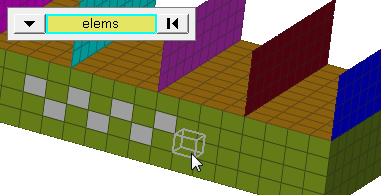
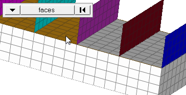
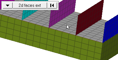
| entity selector | Select the data type
of the entities to find. When you select nodes or elems,
click the switch to change the selection mode.
|
| numbers | Display the numbers of the entities. |
| found nodes: on mark / temp nodes | Only displays when nodes is chosen as the entity. |
| free lines / surf edges | Only displays when lines is chosen as the entity |
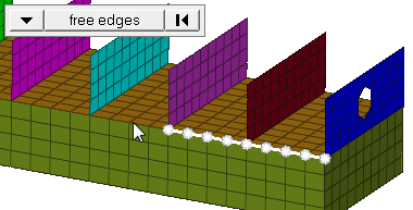
| free edges | Only displays when surf edges is chosen. |
| shared edges | Only displays when surf edges is chosen. |
| non-manifold edges | Only displays when surf edges is chosen. |
| suppressed edges | Only displays when surf edges is chosen. |
| display: only connector | Only displays when connectors is chosen as the entity. |
| display: connector and FE | Only displays when connectors is chosen as the entity. |
| face angle / individual selection |
|
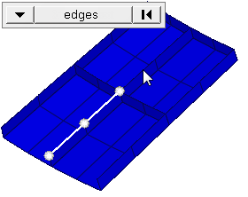
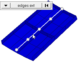
| edge angle |
Split edges that belong to a given face. When the edge
angle is 180 degrees, edges are the continuous boundaries of faces. For smaller
values, these same boundary edges are split wherever the angle between segments
exceeds the specified value. A segment is the edge of a single element.
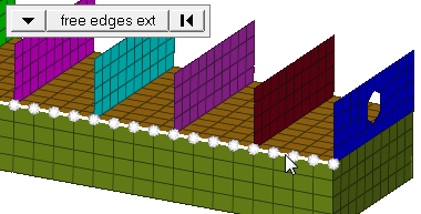
Important: Only available when the entity selector is set to nodes and the
selection mode is set to free edges, free edges ext, edges, or edges
ext.
|
Find Attached Subpanel
Use the Find Attached subpanel to find entities that are attached to other FE or
geometry entities. For example, after you have selected an element, you may use this
function to view the elements that are attached to it, allowing you to move
progressively through the model, row by row.
| Option | Action |
|---|---|
| entity selector | Select the data type of the entities to find. |
| attached to selector | Select the data type
of the entities to which the entities you want to locate are
attached. When you select nodes or elems, click the switch to
change the selection mode.
|
| numbers | Display the numbers of the entities. |
| found nodes: temp nodes/ on mark | Only displays when nodes is chosen as the entity. |
| face angle / individual selection |
|
| edge angle |
Split edges that belong to a given face. When the edge
angle is 180 degrees, edges are the continuous boundaries of faces. For smaller
values, these same boundary edges are split wherever the angle between segments
exceeds the specified value. A segment is the edge of a single element.
Important: Only available when the entity selector is set to nodes and the
selection mode is set to free edges, free edges ext, edges, or edges
ext.
|
Between Subpanel
Use the Between subpanel to find entities that are shared by two or more of the
selected entities. For example, you could find nodes that are shared between
selected components or surfaces, and so on.
| Option | Action |
|---|---|
| nodes / connectors | Select the data type of the entities to find. |
| entity selector | Select the data type
of the entities to which the entities you want to locate are
between. When you select nodes or elems, click the switch
to change the selection mode.
|
| numbers | Display the numbers of the entities. |
| face angle / individual selection |
|
| edge angle |
Split edges that belong to a given face. When the edge
angle is 180 degrees, edges are the continuous boundaries of faces. For smaller
values, these same boundary edges are split wherever the angle between segments
exceeds the specified value. A segment is the edge of a single element.
Important: Only available when the entity selector is set to nodes and the
selection mode is set to free edges, free edges ext, edges, or edges
ext.
|