Edge Edit Panel
Use the Edge Edit panel to alter the connectivity status (topology) of adjacent surface edges, and stitch or split surfaces, replace fillets with corners, and suppress or eliminate redundant edges.
Location: Geom page
Surface Edge Topology
- Free (red)
- The surface edge is not connected to any other surface edge. The mesh generated across a free edge boundary will not be connected.
- Shared (green)
- The boundary between connected surfaces (sometimes referred to as "stitched together").
- Suppressed (blue)
- A manifold shared edge will be disregarded by the meshing process, in effect making a single larger surface out of two individual surfaces.
Topology Display
When entering any panel where the primary function is editing geometry, the surface topology display mode is activated by default. In this mode, the surface edges are colored according to their topology state. The default color assignments are red for free edges, green for shared edges, yellow for non-manifold edges and a blue dotted line for suppressed edges.
Subpanel Organization
You can move freely between subpanels. Your work on one subpanel will not be lost if you switch to a different subpanel. However, similar settings will not be shared between subpanels, so for example changing the cleanup tolerance in one subpanel does not change it in any of the others. In some cases, changes will be reflected immediately in your model as you select edges; in others, one or more green command buttons on the right edge of the subpanel can be used to execute the function once all criteria have been specified.
Toggle Subpanel
Use the Toggle subpanel to toggle edges from one state to another. The topology state can be advanced from free to shared to suppressed by clicking with the left mouse button. Conversely, the state can be regressed from suppressed to shared to free by using the right mouse button.
Exactly what state an edge takes on depends on its current state. Adjacent free edges can be advanced to shared edges with the left mouse button, provided the two edges are within the same space based on the cleanup tolerance setting. The tolerance is used to create a search sphere around the point that is clicked. If another free edge is found, it is considered for a pairing. Any paired edges are checked for an appropriate match along their length based on the cleanup tolerance. The shared edge resulting from this toggle operation will be at the location of the free edge that is clicked.
Left-clicking a shared edge will result in a suppressed edge. Left clicking a non-manifold edge has no effect, since the mesh must have nodes along such a boundary. Right-clicking a suppressed edge reverts that edge to the shared state. Right-clicking a shared edge releases the edge to the free state.

- Convert two free (red) edges to one shared (green) edge.

- Convert a suppressed (blue) edge to a shared (green) edge.
| Option | Action |
|---|---|
| at cursor: edge | Select an edge. |
| cleanup tol |
Specify a value, in model units, above which separate edges
will not be combined, toggled, replaced, or equivalenced. Edges that are this
distance or less from each other will be altered as appropriate to the subpanel,
while those further than this distance from each other will remain unchanged.
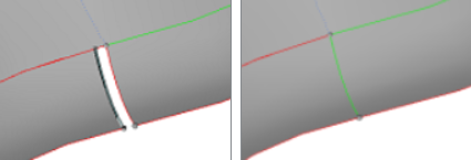 Figure 1. Example: Cleanup Tol. With tolerance 0.1, the gap (size 0.625) remains. With tolerance 0.7, it
closes as the selected edge is toggled to be shared with its nearest
neighbor.
Figure 1. Example: Cleanup Tol. With tolerance 0.1, the gap (size 0.625) remains. With tolerance 0.7, it
closes as the selected edge is toggled to be shared with its nearest
neighbor. |
(Un)Suppress Subpanel
| Option | Action |
|---|---|
| lines selector | Select the surface edges to suppress or unsuppress. |
| break angle | Used to preserve
geometric features within the selection; if the break angle
between the normals of adjacent surface edges exceeds the set
value, the edges will not be suppressed. For shared edges,
this is the maximum tangential angle between two surfaces at
the shared edge. Edges of surfaces exceeding this angle are
not suppressed.
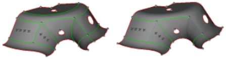 Figure 2. Example: Break Angle. With a Break Angle of 0.1, some of the shared edges are suppressed (especially on the right side) but many remain. |
Replace Subpanel
Use the Replace subpanel to move one edge line to the same edge as another, effectively combining the two edges into a shared edge at the location of one of the original edges.
This functionality provides additional control over the toggle function. Individual selections are made for the line to move and the line to retain. The resulting shared edge will be at the location of the line selected as retained.
| Option | Action |
|---|---|
| moved edge: lines selector | Select the surface edges to suppress or unsuppress. |
| retained edge: line selector | Select the edge line to move the other lines to. |
| cleanup tol |
Specify a value, in model units, above which separate edges
will not be combined, toggled, replaced, or equivalenced. Edges that are this
distance or less from each other will be altered as appropriate to the subpanel,
while those further than this distance from each other will remain unchanged.
Figure 3. Example: Cleanup Tol. With tolerance 0.1, the gap (size 0.625) remains. With tolerance 0.7, it
closes as the selected edge is toggled to be shared with its nearest
neighbor. |
Equivalence Subpanel
Use the Equivalence subpanel to search for free edges and combine them with a matching edge within the cleanup tolerance. The surfs selector allows selection of surfaces to check using any of the extended selection options.
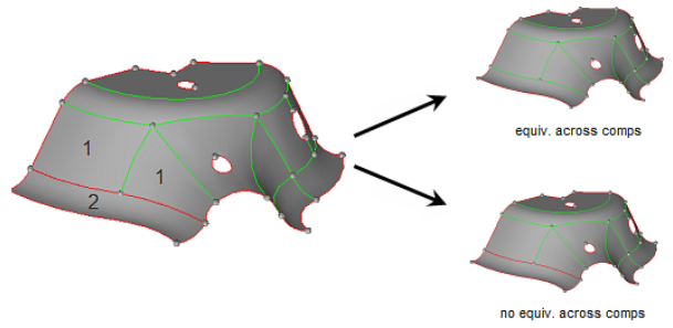
Figure 4. Surfaces Selected from Components 1 and 2
| Option | Action |
|---|---|
| surfs selector | Select the surface to check. |
| geometry stitching | The surface stitching
options define whether or not free-edge pairs are combined
according to the following rules:
|
| cleanup tol | The maximum distance
between free surface edges for them to be considered a pair. Specify a value, in model units, above which separate edges
will not be combined, toggled, replaced, or equivalenced. Edges that are this
distance or less from each other will be altered as appropriate to the subpanel,
while those further than this distance from each other will remain unchanged.
Figure 5. Example: Cleanup Tol. With tolerance 0.1, the gap (size 0.625) remains. With tolerance 0.7, it
closes as the selected edge is toggled to be shared with its nearest
neighbor. |
| equiv free edges only | Restrict this
operation to free surface edges only. Otherwise, a free edge
that matches a shared edge can be combined to form a
non-manifold edge. This option prevents shared edges from
being equivalenced; only free edges will be
equivalenced.
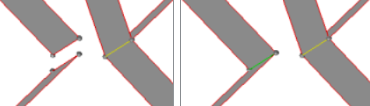 Figure 6. Example: Equiv Free Edges Only. All surfaces are selected, but only the two free edges on the left are made equivalent with each other. The shared non-manifold edge on the right remains unchanged. |
Unsplit Subpanel
| Option | Action |
|---|---|
| at cursor: line selector | Select a single line to unsplit and carry out the operation immediately upon selection. |
| multiple edges: lines selector | Select multiple lines (with extended entity selection) and carry out the operation upon clicking untrim. |
Edge Fillets Subpanel
Use the Edge Fillets panel to remove fillets from surface edges.
- The left side of the panel presents a search and select option to automatically identify surface edge fillets.
- The right side presents a trim intersect option in which you manually remove the edge fillet by selecting the fillet endpoints.
The option to remove fillets can be performed on as many fillets as you wish; all fillets in the model meeting the criteria you specify will be located and selected. Replacing a fillet with a trim-intersection corner, however, is a manual process that can only be performed on one fillet at a time.
The Search function requires selection of the surfaces to check for edge fillets. The minimum and maximum radius values bound the search to avoid looking for very small or very large fillets. The minimum angle sets a minimum arc length for a fillet to be identified.
Once surfaces have been selected and the search criteria entered, click find to identify any edge fillets meeting the search criteria. Fillets will be identified with the letter "F" at the arc center and radial lines indicating the beginning and end points on the surface edge. At this point, the fillets selector is active with all identified fillets pre-selected. Any fillets that you do not wish to remove may be de-selected by right-clicking them in the modeling window.

Figure 7.
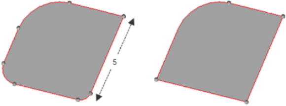
Figure 8. . Fillets with radii greater than .001 but less than 1.1 were found and removed, resulting in the large top-corner fillet (radius 2) remaining unchanged.
| Option | Action |
|---|---|
| surfs selector | Select the surface to find. |
| fillets selector | Select the fillet to find. |
| min radius | Only fillets with a radius of at least this length will be found. |
| max radius | Only fillets with a radius of less than this length will be found. |
| min angle | Only fillets with an arc of at least this number of degrees will be found. |
| all / rounds / fillets | Choose whether to find fillets, rounds, or all.
Fillets are typically quarter-circles or less, while rounds are quarter- to-half-circles. All searches for both types. |
| trim-intersect: node selector | Select one of the end points of the fillet you wish to remove by clicking the fillet's line in the modeling window. |
| trim-intersect: node selector (second) | Select the other end
point of the fillet you wish to remove by clicking the fillet's
line in the modeling window. A second temporary node is created, and the fillet is removed to be replaced by a corner. The corner is formed by extending the two lines on which the nodes you selected lie, until they touch. |
By Feature Subpanel
Use the By Feature subpanel to combine surfaces based on geometric features. Edges meeting the criteria specified on this subpanel will be suppressed so that the corresponding surfaces are treated as being continuous by the meshing engine. Edges falling outside the criteria remain unmodified.
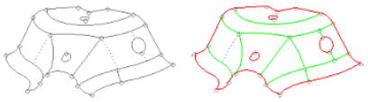
Figure 9. . With all surfaces selected, the suppressed (dotted line) edges on the right side become shared because they exceed the angle, but the one on the left remains since it does not.
| Option | Action |
|---|---|
| surfs selector | Select the surface to modify. |
| close / leave orphan | Choose whether or not you wish the geometry engine to attempt to create closed loops from any non-closed features, such as an incomplete circle or u-shaped feature. |
| angle surfs | Preserve shared (green) edges between surfaces whose break angle (difference in surface normal direction) is more than the input value. These normals are calculated and compared at an offset distance from their common shared edge. You can adjust both the angle and the offset distance. |
| offset surfs | Specify the offset distance to be used in conjunction with the angle surfs value. |
| min fillet/max fillet | Preserve the shared (green) edges along the line of tangency of the surface fillet and its adjacent surfaces. The faces that comprise the length of the fillet are combined (their edges are suppressed). You can adjust the minimum and maximum fillet radii to be considered. |
| angle vertex | Check angle vertex to
preserve the shared (green) edges leading away from a surface
vertex whose exterior angle is greater than a user-specified
angle. This option works on only suppressed edges and
unsuppresses them where this criterion fails. Therefore, if you
use move mode with this option alone it will not provide
effective results.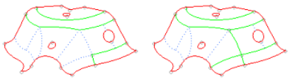 Figure 10. . The two suppressed (dotted) edges in the center-right of the model are unsuppressed (solid green) when using an angle vertex value of 220 degrees. |
| shape ratio | Check for surfaces
that have shape ratio (ratio of the lengths of opposite edges)
greater than the user-specified value. In such a case, any
suppressed edges present inside that surface are unsuppressed to
reduce the shape ratio. Similar to vertex angle tool, this
option works effectively with update mode or in combination with
other options.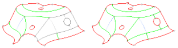 Figure 11. . The small suppressed edges near the circular hole are unsuppressed, making the surface ratio fall within the specified threshold. |
| min edge | Detect edges that are
smaller than the user-specified value. The edges that are
detected as small are fixed in three ways:
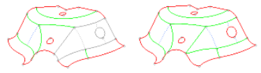 Figure 12. |