Split Panel
Use the Split panel to split plates or solid elements. In addition, hexa elements can also be split using a technique that moves progressively through a row of elements in the model.
Location: 1D, 2D, and 3D pages
Plate Elements Subpanel
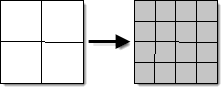
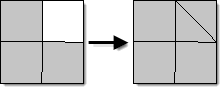
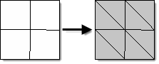
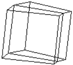 Figure 1. Elements Selected |
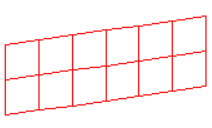 Figure 2. Plate Elements Split |
| Option | Action |
|---|---|
| elems selector | Select elements to split. |
| use inferred surface if no geometry exists | When elements are split using this function, the new nodes that are created are placed on the element's underlying geometric surface, if it exists. If there is not a geometric surface, the new nodes are placed midway between the original corner nodes unless the use inferred surface if no geometry exists checkbox is activated, in which case the new nodes are placed upon the inferred surface of the elements. |
| Reverse split direction | Reverse the direction
quad elements are split. Note: Available when divide quads is
selected.
|
| split method options | Select a split
method. When you split elements whose nodes are associated to a surface, the new nodes created are also on the surface. To associate a node to a surface, use the Node Edit panel. All split operators work on both first and second order elements.
|
| split all connected 1D | Split a connected 1D
element at the midpoint of its sides. Note: Available when the
split method is set to split all sides.
|
Solid Elements Subpanel
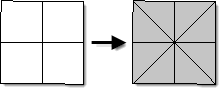
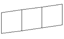 Figure 10. Elements Selected |
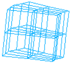 Figure 11. Elements Split into Hexas |
| Option | Action |
|---|---|
| elems selector | Select the elements to split. |
| split method options | Select a method for
splitting solid elements.
All split operators work on both first and second order elements. |
Hexa Elements Subpanel
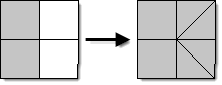
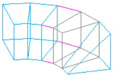 Figure 12. Elements Selected |
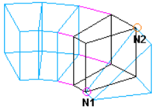 Figure 13. Opposing Corners Selected on Face of Hexa Element. Select opposing corner nodes on the face of the hexa element to indicate how to split the element. |
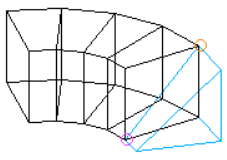 Figure 14. Elements Highlighted. The hexa elements that will be affected by the split command are highlighted. |
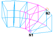 Figure 15. Elements Split |
| Option | Action |
|---|---|
| Propagate to | Select
All or the elements
selector.
|
| Element edge by node pairs | Select nodes to define the direction of split/combine/delete. Two subsequent node selections define a direction. You can select multiple node pairs simultaneously, but they should be neighboring nodes. Choosing by Path allows you to define multiple splits and works for split only. |
| Operations | Select one of the
following:
|
Hexa Elements Command Buttons
| Option | Action |
|---|---|
| Split/Combine/Delete | Executes the selected operation. |
| Preview candidate | Isolates a possible candidate for split/combine/delete. |
| Reject | Undo the operation. |
Refine Elements Subpanel
HyperLife Weld Certification automatically maintains legal connectivity to shell elements that are adjacent to those that are split.
If the refined elements are attached to a surface, HyperLife Weld Certification makes sure that the new elements are also attached to the same surface. If they are not, HyperLife Weld Certification infers a surface from the mesh, and positions the new nodes so that they fall on the implicit surface.
HyperLife Weld Certification calculates chordal deviation using the algorithm described in the Check Elements panel.
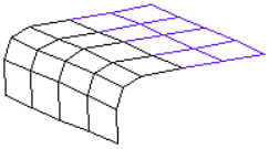
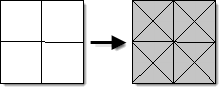
Figure 16. Elements Selected
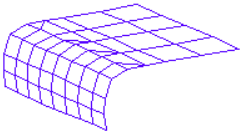
Figure 17. Elements Split using Target Element Size
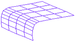
Figure 18. Elements Split using Chordal Deviation
| Option | Action |
|---|---|
| elems selector | Select the elements to split. |
| refinement option | Select a refinement option (target element size or chordal deviation). |
| split all connected 1D | |
| target element edge length | Specify the target element size. |
| max chordal deviation | Specify the target chordal deviation. |
| min element edge length | Specify a minimum edge length which determines how far HyperLife Weld Certification is allowed to go while attempting to satisfy the request accuracy. |
Command Buttons
| Button | Action |
|---|---|
| return | Exit the panel. |