Renumber Panel
Use the Renumber panel to renumber entities. You may also enter a value by which to offset the IDs of entities.
Location: Organize menu bar
When the ID to be assigned to an entity is already assigned to another entity, HyperLife Weld Certification adds the increment to the ID until a unique ID is found. Because of this, it may be necessary to move the entities out of the way by initially renumbering all of the entities starting with a large ID, and then renumber again with the desired IDs.
Single Subpanel
| Option | Action |
|---|---|
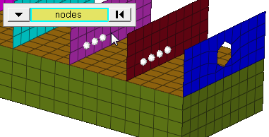
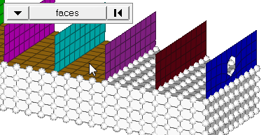
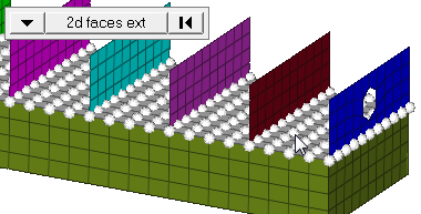
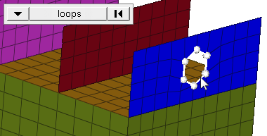
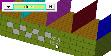
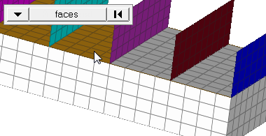
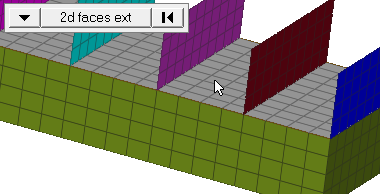
| entity selector | Select the type of
entity to renumber, then select the entities that you wish to
renumber. When you select nodes or elems, click the switch to
change the selection mode.
|
| start with = | Specify the starting ID for the entities you selected. |
| increment by = | Specify the value by which to increment the entity IDs. |
| offset = | Specify the value with
which to offset the selected entities. It is possible to offset by both positive and negative values, provided that the offset IDs of all selected entities are greater than zero. |
| face angle / individual selection |
|
| edge angle |
Split edges that belong to a given face. When the edge
angle is 180 degrees, edges are the continuous boundaries of faces. For smaller
values, these same boundary edges are split wherever the angle between segments
exceeds the specified value. A segment is the edge of a single element.
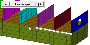
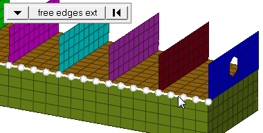
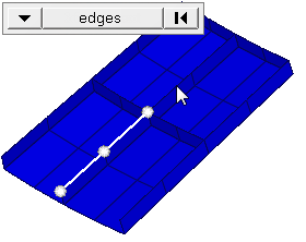
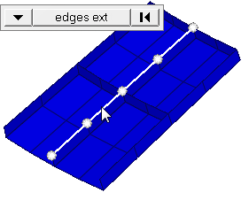
Important: Only available when the entity selector is set to nodes and the
selection mode is set to free edges, free edges ext, edges, or edges
ext.
|
All Subpanel
| Option | Action |
|---|---|
| start with = | Specify the starting ID for the entities you selected. |
| increment by = | Specify the value by which to increment the entity IDs. |
| offset = | Specify the value with
which to offset the selected entities. It is possible to offset by both positive and negative values, provided that the offset IDs of all selected entities are greater than zero. |
Command Buttons
| Button | Action |
|---|---|
| renumber | Renumber the selected entities according to the input settings. |
| min/max | Causes the total
number and the range of numbers of the selected entity type to
display as a message in the status bar. If entities are
selected, the total number and range of numbers includes only
the selected entities; otherwise, all entities of the type
specified by the entity switch are counted. Note: Available in
the Single subpanel.
|
| offset | Offset the numbers by the value specified in offset = each time you click offset. |
| reject | Undo the renumbering of entities. |
| return | Exit the panel. |