Shape Panel

Use the Shape panel to create shape design variables and associate them to a shape for shape optimization.

Location: Analysis page > Optimization panel
Note: Only available in the OptiStruct solver interface.

Shapes must be defined previously using the Perturbations panel or the HyperMorph module.

Note: When creating shape design variables for the Madymo-XML format, the original XML file must be imported and exported from HyperLife Weld Certification. This is necessary, as HyperLife Weld Certification cannot handle the duplicate node IDs, which the Madymo-XML format allows. If this is not done, the shape design variables may refer to the wrong nodes.
The Shape panel can also be used to export shape design variables and shapes in different formats for use in optimization software other than OptiStruct. These options are set on the Export subpanel.
Analysis Code Sub-Code Remarks
OptiStruct, Nastran, Genesis None, long, force, moment, temperature For shape optimization and variable loading.
HyperStudy, Templex OptiStruct, HyperForm, Nastran, Dynakey, Dynaseq, Radioss, PAM-CRASH 2G, Marc, ANSYS, Abaqus, Abaqus2D, Madymo, Madymo-XML, Fluent, Permas, Ideas For shape parameterization with HyperStudy, Templex, and HyperOpt/Generic.
HyperOpt OptiStruct, Abaqus, Nastran For shape optimization with HyperOpt/ OptiStruct, HyperOpt/ Abaqus, and HyperOpt/ Nastran.

Desvar Subpanel

Option Action
create / update Select whether to create desvars or update existing ones.
desvar = Specify a name for the new design variable, or click the button to select an existing one.
Note: Available when creating or updating a single desvar.
initial value = Specify the initial value for the design variable.
lower bound = Specify the upper boundary for the design variable.
upper bound = Specify the lower boundary for the design variable.
move limit default / move limit = Choose how the movement limit is determined.

If you select move limit =, you must specify a limit value.

no ddval / ddval = Choose whether or not to use a discrete design value.

If you choose ddvale =, click the button to select an existing ddvals.

shape = Select a predefined shape that you wish to apply.
Note: Available when creating or updating a single desvar.
single desvar / multiple desvars /non-linear desvars Choose a method for creating/updating design variables.

In the case of non-linear design variables, how the variable is applied (via the by constraint / by system / by mid-shape switch that displays for nonlinear desvars.)

shapes Select the desired shapes.
Note: Available when multiple desvars is selected.
by constraint / by system / by mid-shape Shapes are saved as linear perturbations in HyperLife Weld Certification, therefore additional information is required to determine the intended non-linear path of each node when a shape is applied at values other than zero and one. Some nodes move along constraints while others travel about the z-axis of a cylindrical coordinate system. Select the non-linear shape creation method according to how you intend the nodes to move.
by constraint
Assumes that constraints, such as those which force nodes to move along or are bounded by a line, plane, surface, mesh, or equation, make the shape non-linear. When you click create HyperLife Weld Certification applies each selected shape a number times between the lower and upper bounds, applying the constraints each time. From these applications, the non-linear path for each node will be calculated for each shape and up to four new shapes and design variables (per shape) will be generated which, through equations which link them together, will describe the non-linear motion of the shapes as they are affected by the constraints. For bounded style constraints, where nodes are allowed to move up to but not past a feature such as a surface, you should create any shape which is affected by such constraints with the limiting constraints made inactive. In other words, the nodes should pass through the constraint when the shape is applied. Then, before creating the non-linear shapes, make the limiting constraints active again. This will ensure that the path of the nodes will be non-linear, moving up to the constraint and then stopping, rather than linearly moving up to the constrained position. You can set which constraints are active and inactive in the HyperMorph panel > Morph Options panel. Due to the limitations of simulating bounded constraints via equations, the constrained nodes may stop slightly short or pass slightly beyond the constraints for some values of application during optimization.


Figure 1. Two Meshes Constrained to a Cylindrical Surface. The mesh on the left slides along the surface, while the mesh on the right is bounded by the surface. Both shapes need to be converted into nonlinear design variables to perform during optimization as they do during morphing. The shape on the right will move the mesh through the surface if the bounding constraint is inactive. This is how shapes to be converted to nonlinear shapes should be defined when bounding constraints are used. The bounding constraint must be made active when creating non-linear design variables.
by system
Intended for shapes which were created by rotating the mesh using the angle or arc angle options in the HyperMorph panel > Alter Dimensions panel > Shapes panel which were created with respect to a cylindrical coordinate system, or any shapes whose nodes are intended to move in the r-theta-z directions rather than the x-y-z directions. To use this option you must select a local coordinate system about which the selected shapes rotate. HyperLife Weld Certification will then determine the non-linear paths of the nodes for each shape as they travel around the local coordinate system and create up to four new shapes for each shape which, through equations which link them together, describe the non-linear paths of the nodes.


Figure 2. Two Shapes Created with Respect to a Cylindrical Coordinate System. n the top figure, the arc angle of the mesh is changed and in the bottom figure, the radius of the mesh is changed. Both shapes act with respect to the cylindrical coordinate system, the first by moving nodes in the theta direction and the second by moving nodes in the radial direction. These shapes should be converted to non-linear design variables using the by system option so that the mesh maintains its true curvature during optimization.
by mid-shape
Create a non-linear shape described by two shapes. One shape represents the non-linear shape when it is applied with a multiplier of one. The other shape represents the non-linear shape when it is applied with a multiplier of one-half. HyperMorph will interpolate the non-linear paths of the nodes as they travel from the undeformed position to the mid-shape position to the full shape position. HyperMorph will then create three shapes which, through equations which link them together, describe the non-linear paths of the nodes.


Figure 3. Non-Linear Path. The non-linear path (yellow) for a node is calculated as starting at the undeformed position, passing through the half-shape position (blue), and finishing at the full-shape position (magenta).
For all three options, all the necessary design variables, equations, and dlink2 cards are created to support optimization. You do not need to create design variables for your original shapes. Also, if you are converting two or more shapes into non-linear shapes which control the same nodes, it is likely that when more than one shape is applied at the same time that the nodes will violate any given constraints or movement with respect to a local coordinate system. For this reason, HyperMorph creates one more shape for each pair of overlapping shapes which, when linked to the overlapping shapes through an equation, compensate for the interaction of the shapes. In order to activate this feature, you must create your non-linear design variables for all the desired shapes at the same time. Also, since linear shapes may conflict with non-linear shapes when they are both applied, such as when shapes which move nodes radially are applied at the same time as shapes which move nodes about an axis, you should create design variables for all your shapes, linear and non-linear, at the same time.


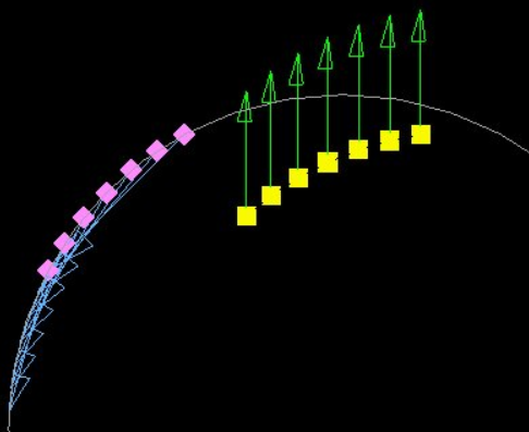
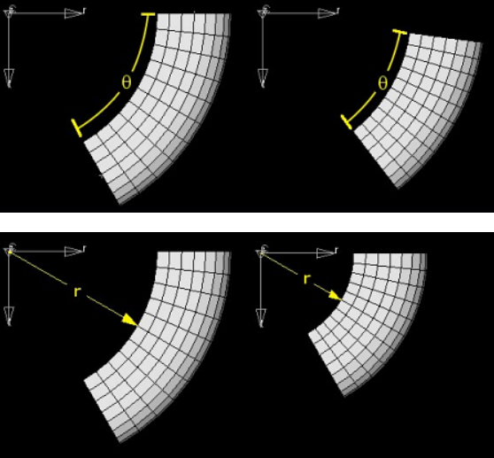
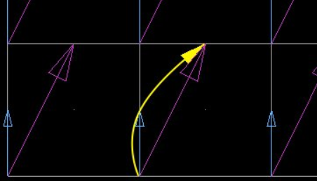
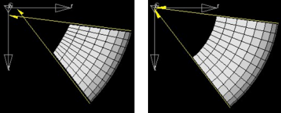
Figure 4. Arc Angle Shape Change Applied Simultaneously with a Radius Shape Change. In the left figure the two shapes are applied with no compensation. Notice how the sides of the mesh no longer line up with the axis of the local coordinate system. In the right figure the compensation shape has been applied. Notice how the sides of the mesh now line up with the center axis of the local coordinate system. If both shapes are converted into non-linear design variables at the same time, the compensation design variable will be generated and integrated into the optimization automatically.
For each non-linear shape up to four shapes will be created. These will be named o#a, o#b, o#c, and o#d where # is the ID of the original shape. The shape named o#a is linked to an independent design variable while the other shapes are linked to dependent design variables. If you wish to apply the dependent shapes by amounts calculated using the deqatn cards for a given value of the independent shape go to the HyperMorph panel > Shapes panel > Apply Shapes panel and select only the o#a shape to be applied. When you click apply, a message will display asking "Apply shapes linked though desvars and dlinks.”. Click yes to enable HyperMorph to apply o#b, o#c, and o#d automatically by the amounts necessary to make the shapes function as they would during an optimization. This works for both the by factor and interactive options, allowing you to visualize how the non-linear variables will perform. Also, you can apply more than one o#a shape as well as any overlapping linear shapes and HyperMorph will apply the compensation shapes between the selected independent shapes in addition to the dependent shapes for the independent shapes. The compensation shapes will be named r#r# where the #’s are the IDs of the two overlapping shapes. To apply linked shapes in HyperLife Weld Certification batch mode use the command *morphshapelinkedpush to assign values for the independent shapes and *morphshapelinkedapply to apply them.

When applied during optimization, the non-linear shapes will be close to, but probably not exactly aligned with, the intended node paths. Although the generated shapes and equations have been optimized to minimize the amount of error between the intended node paths and the actual node paths it is not possible to precisely mimic every non-linear shape using a combination of linear ones. However, this feature should allow sufficient fidelity for most optimization applications.

Shapes to be converted into non-linear shapes perform best when they have either a lower bound or upper bound of 0.0, but good fidelity can be achieved for shapes which have a negative lower bound and positive upper bound. However, non-linear shapes which sweep out an arc of more than 90 degrees may not give good fidelity for intermediate values.

designvars Select the design variables that you wish to alter.
Note: Available when updating multiple desvars.

Export Subpanel

Option Action
file: Specify a file name for the exported file.
analysis code Select the desired export analysis code.
sub-code Select the desired export analysis sub-code.

Command Buttons

Button Action
create Create the new shape design variable.
reject Undo the most recent shape design variable creation.
update Update an existing shape variable to use the current input settings.
animate Open the Deformed panel to post-process the results.
review Click this button to display a list of existing shape design variables. Select one to display its settings in the input fields.
undo morphing  
export as Open a standard file browser dialog to select a specific directory and/or filename.
return Exit the panel.