Connector Creation Panels
Overview of the structure in the Spot, Bolt, Seam and Area panels.
- spot/bolt/seam/area
- The connector of the appropriate type is both created and realized simultaneously.
- create
- The connector of the appropriate type is only created.
- realize
- An existing connector of the appropriate type is only realized.
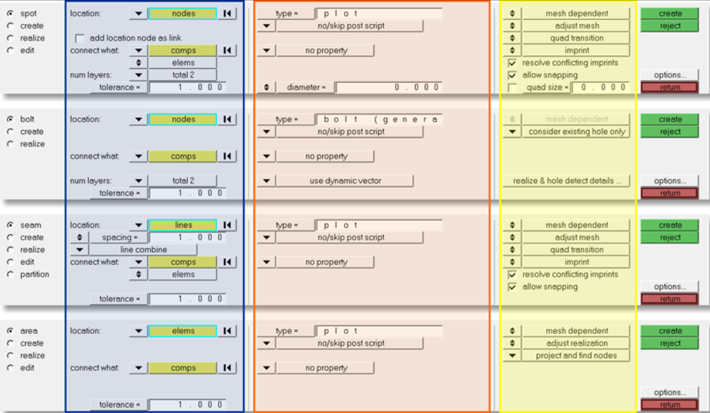
Figure 1. Connector Module Structure. The subpanels are organized into three columns, which are indicated with colored boxes.
First Column (Blue)
- location
- link candidates (link entity type, link state)
- number of layers (only for spots and bolts), and
- tolerance
- spacing/density
- Defines how the test points should be distributed along a connector line. At each test point a separate realization is performed. This is also available for spot or bolt connectors.
- split to points
- Available for any kind of elongated connector location like line, linelist, or nodelist. The test points are distributed along this line, but single connectors instead of a line connector are created.
- add location node as link
- Available only for spots defined at node locations. The selected node is stored on the connector as link entity.
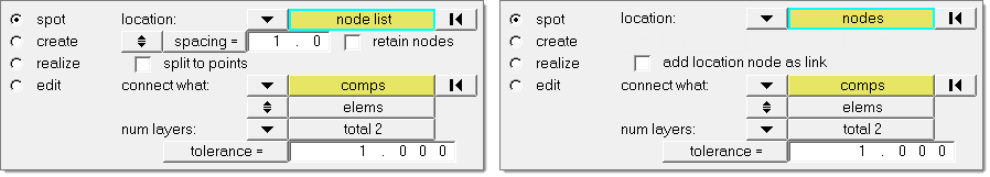
Figure 2.
Second Column (Orange)
This column contains everything related to realization type, post script, and property assignment.
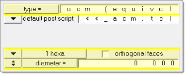
Figure 3. Realization Options
Many custom realization types include a certain post script. If such a realization type is chosen, the default post script is set to the appropriate post script. These types of post scripts typically manage the organization and property assignment of the FE representation.
- default post script
- Default for any realization type having a post script defined in its FE
configuration, though this option can be changed (sometimes you may wish to skip the
predefined post scripts or to use your own).
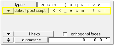
Figure 4. Default Post Script - no/skip post script
- Default for all realization types without any post script defined. No post script is
used. When this option is chosen, several additional entry controls appear.
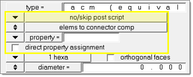
Figure 5. No/Skip Post Script - user post script
- You must specify your own .tcl file to be used. Such a file can perform a special treatment on the FE representation.
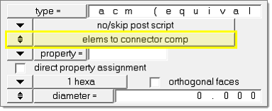
Figure 6. Element Destination Options
- elems to current comp
- The newly created elements are organized into the current component.
- elems to connector comp
- The newly created elements are organized appropriate to the connector component.
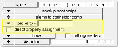
Figure 7. Property Treatment Options
- property
- Select a property to assign to all newly created elements.
- no property
- No property is created.
- direct property assignment
- Directly assigns the property.
Third Column (Yellow)
This column contains options related to the final connection to the link entities. This column is the same for all of the different realize subpanels.
The realization methods can be chosen in every subpanel where a connector realization can be performed. These subpanels are always the 1st and 3rd subpanel in the Spot, Bolt, Seam, and Area panels. In each case, the first subpanel creates and subsequently realizes the connector, while the third subpanel realizes preexisting connectors. All of these subpanels are divided into three sections; the right section is the one with the different realization methods.