/SECT
Block Format Keyword Sections are used to output the force and moment of a cross section defined by a group of nodes and groups of elements.
Section data saved in one simulation can be read and applied in a second simulation.
Format
| (1) | (2) | (3) | (4) | (5) | (6) | (7) | (8) | (9) | (10) |
|---|---|---|---|---|---|---|---|---|---|
| /SECT/sect_ID/unit_ID | |||||||||
| sect_title | |||||||||
| node_ID1 | node_ID2 | node_ID3 | grnd_ID | ISAVE | frame_ID | ||||
| file_name | |||||||||
| grbric_ID | grshel_ID | grtrus_ID | grbeam_ID | grsprg_ID | grtria_ID | Ninter | Iframe | ||
| (1) | (2) | (3) | (4) | (5) | (6) | (7) | (8) | (9) | (10) |
|---|---|---|---|---|---|---|---|---|---|
| int_ID1 | int_ID2 | int_ID3 | int_ID4 | int_ID5 | int_ID6 | int_ID7 | int_ID8 | int_ID9 | int_ID10 |
Definitions
| Field | Contents | SI Unit Example |
|---|---|---|
| sect_ID | Section
identifier. (Integer, maximum 10 digits) |
|
| unit_ID | Unit Identifier. (Integer, maximum 10 digits) |
|
| sect_title | Section
title. (Character, maximum 100 characters) |
|
| node_ID1 | Node identifier N1 defining the local output system of the section. 2 (Integer) |
|
| node_ID2 | Node identifier N2 defining the local output system of the section. 2 (Integer) |
|
| node_ID3 | Node identifier N3 defining the local output system of the section. 2 (Integer) |
|
| grnd_ID | Node group identifier
which defines the nodes used in the section calculation. Not used if frame_ID is defined. (Integer) |
|
| ISAVE | Saving or reading the
section data from file_name flag.
(Integer) |
|
| frame_ID | (Optional) Moving frame
identifier. Must be defined using nodes
/FRAME/MOV. The xy plane of the frame
intersects the elements groups to automatically define the nodes and
elements used in the section calculation. If node_ID1 - node_ID3 are not defined then the frame is also used as the output system
of the section. (Integer) |
|
| Time step for saving the
section data used with
ISAVE
=1 or 2. Default = time step of the simulation (Real) |
||
| Exponential moving average
filtering constant (0 <
< 1). Smaller values result in
more filtering Only used when applying the displacements to a section using ISAVE= 100 or 101. Recommended value = 0.62832 (refer to Filter in the User Guide) Default = No filtering (Real) |
||
| file_name | Root name of the file
which contains the flag output. The section file will be named
file_nameSC01. Default = Runname (where Runname is the prefix to the Engine file, Runname_0001.rad) (Character, maximum 100 characters) |
|
| grbric_ID | Brick group
identifier. (Integer) |
|
| grshel_ID | Shell group
identifier. (Integer) |
|
| grtrus_ID | Truss group
identifier. (Integer) |
|
| grbeam_ID | Beam group
identifier. (Integer) |
|
| grsprg_ID | Spring group
identifier. (Integer) |
|
| grtriag_ID | Triangle group
identifier. (Integer) |
|
| Ninter | (Optional) Number of
interfaces. Default = 0 (Integer) |
|
| Iframe | Flag defining the center
of the local system used in the calculation of the section forces
and moments. 3 The section output is in the
local system with the center defined as:
The section output is in the global system with the
center defined as:
(Integer) |
|
| int_ID1, int_ID2, ..., int_IDn | Optional interface
identifiers, if Ninter >
0. (Integer) |
Comments
- A section is defined by a node group
and element groups and can be defined manually or automatically.
- Manually: The section nodes (grnd_ID and elements (grbric_ID, grshel_ID, grtrus_ID, ...) are user-defined. HyperMesh and HyperCrash will automatically create the groups but, they should be reviewed. Using this method, the user creates the node and element groups that define the section cut. Typically, nodes in the normal direction of the section are used in the node group.
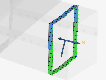
Figure 1. Elements and Nodes Selected Manually - Automatic: A local system frame_ID can be defined which cuts the defined groups of elements (grbric_ID, grshel_ID, grtrus_ID, ...). In this case, the element groups contain all the elements in the area of the section. The nodes and elements on the xy plane of the local system are automatically defined for the section calculation. The nodes and elements used in the section are then output in the Starter output file. The cutting plane is the xy plane of the system.
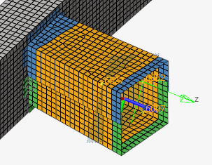
Figure 2. Element Group (in orange) defined for a section cut defined using a local system
- Manually:
- The forces and moments from the sections will be stored in the time history file and requested using /TH/SECTIO.
- The local force and moment output
system of the section is defined using 3 nodes or via a local moving system
(frame_ID). These three nodes should be nodes on the
section plane, so their position is updated when the section moves. When using
the Cross-Section Assistant in HyperMesh to create
the section, the 3 nodes are automatically selected. When defined using node_ID1 - node_ID3, the definition using nodes:
- Nodes node_ID1 and node_ID2 define the local x-axis of the section.
- Nodes node_ID1, node_ID2, and node_ID3 define the local plane xy of the section.
- The local y-axis is defined by projecting node_ID3 perpendicular to the local x-axis.
- The intersection of the local x- and y-axis is then the origin of the system.
- Last the section normal is the local z-axis which is perpendicular to
the xy plane:
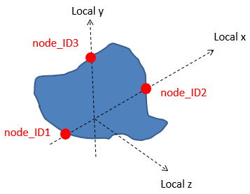
Figure 3. - If frame_ID ≠ 0 and node_ID1-node_ID3 are not defined, then the moving frame_ID is used as the local system. The frame should be a moving frame defined using nodes.
- The center of the section can be redefined using the Iframe option. Refer to Force and Moment Computation in the User Guide for more details.
- Sections can also be used in a cut modeling method where section forces and displacements are saved from a full model and then applied in a second cut model. In the full model, the section information is saved using the ISAVE =1 or 2 option. Then in the cut model, the same section nodes and element groups are defined and the section displacements are applied to the cut model using ISAVE =100 or 101. The cut model is then used to study a detailed area of the full model (RD-E: 5400 Cut Methodology).
- Recommendations:
Pick nodes and elements along the section. If nodes and elements are automatically selected by a preprocessor review what was selected.
Select the 3 nodes for node_ID1-node_ID3 that are defined in the node group.
Define Iframe =2 or 12, the center is the CoG of the section.
Time history output GLOBAL and LOCAL in /TH/SECTIO.