/SECT/CIRCLE
Block Format Keyword A circle section is used to output the force and moment of a cross section defined by a circular disc.
The nodes and elements that define the section are automatically selected by intersecting the groups of elements with a disc.
Format
| (1) | (2) | (3) | (4) | (5) | (6) | (7) | (8) | (9) | (10) |
|---|---|---|---|---|---|---|---|---|---|
| /SECT/CIRCLE/sect_ID/unit_ID | |||||||||
| sect_title | |||||||||
| node_ID1 | node_ID2 | node_ID3 | ISAVE | ||||||
| file_name | |||||||||
| grbric_ID | grshel_ID | grtrus_ID | grbeam_ID | grsprg_ID | grtria_ID | Ninter | Iframe | ||
| (1) | (2) | (3) | (4) | (5) | (6) | (7) | (8) | (9) | (10) |
|---|---|---|---|---|---|---|---|---|---|
| int_ID1 | int_ID2 | int_ID3 | int_ID4 | int_ID5 | int_ID6 | int_ID7 | int_ID8 | int_ID9 | int_ID10 |
| (1) | (2) | (3) | (4) | (5) | (6) | (7) | (8) | (9) | (10) |
|---|---|---|---|---|---|---|---|---|---|
| XM | YM | ZM | |||||||
| Dir_X | Dir_Y | Dir_Z | |||||||
| R | |||||||||
Definitions
| Field | Contents | SI Unit Example |
|---|---|---|
| sect_ID | Section
identifier (Integer, maximum 10 digits) |
|
| unit_ID | Unit Identifier (Integer, maximum 10 digits) |
|
| sect_title | Section
title (Character, maximum 100 characters) |
|
| node_ID1 | Node identifier N1 defining the local output system of the
section. (Integer) |
|
| node_ID2 | Node identifier N2 defining the local output system of the
section. (Integer) |
|
| node_ID3 | Node identifier N3 defining the local output system of the
section. (Integer) |
|
| ISAVE | Saving or reading the
section data from file_name flag.
(Integer) |
|
| Time step for saving the
data used with
ISAVE
=1 or 2. Default = time step of the simulation (Real) |
||
| Exponential moving average
filtering constant (0 <
< 1). Smaller values result in
more filtering. Only used when applying the displacements to a section using ISAVE= 100 or 101. Recommended value =0.62832 (refer to Filter in the User Guide) Default = No filtering (Real) |
||
| file_name | Root name of the file
which contains the flag output. The section file will be named
file_nameSC01. Default = Runname (where Runname is the prefix to the Engine file, Runname_0001.rad) (Character, maximum 100 characters) |
|
| grbric_ID | Brick group
identifier. (Integer) |
|
| grshel_ID | Shell group
identifier. (Integer) |
|
| grtrus_ID | Truss group
identifier. (Integer) |
|
| grbeam_ID | Beam group
identifier. (Integer) |
|
| grsprg_ID | Spring group
identifier. (Integer) |
|
| grtriag_ID | Triangle group
identifier. (Integer) |
|
| Ninter | Number of
interfaces (Integer) |
|
| Iframe | Flag defining the center
of the local system used in the calculation of the section forces
and moments. 3
The section output is in the local system with the center defined as:
The section output is in the global system with the
center defined as:
(Integer) |
|
| int_ID1, int_ID2, ..., int_IDn | Optional interface
identifiers, if Ninter >
0. (Integer) |
|
| XM | X
coordinate of center of the disc (Point M). (Real) |
|
| YM | Y
coordinate of center of the disc (Point M). (Real) |
|
| ZM | Z
coordinate of center of the disc (Point M). (Real) |
|
| Dir_X | X
coordinate of normal vector to the disc. (Real) |
|
| Dir_Y | Y
coordinate of normal vector to the disc. (Real) |
|
| Dir_Z | Z
coordinate of normal vector to the disc. (Real) |
|
| R | Radius of the
disc. (Real) |
Comments
- The elements groups defined will
be intersected by the defined disc. The section nodes are created from the nodes
of those intersected elements, which are on the upside (z > 0) of the plane of
the disc.
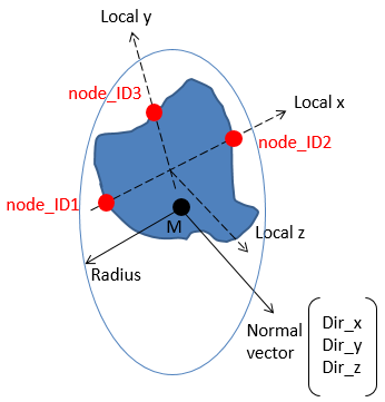
Figure 1. - The forces and moments from the sections will be stored in the time history file and requested using /TH/SECTIO.
- The local force and moment output
system of the section is defined using 3 nodes. These three nodes should be
nodes on the section plane, so their position is updated when the section moves.
When using the Cross-Section Assistant in HyperMesh
to create the section, the 3 nodes are automatically selected.Local system is defined as:
- Nodes node_ID1 and node_ID2 define the local x-axis of the section.
- Nodes node_ID1, node_ID2, and node_ID3 define the local plane xy of the section.
- The local y-axis is defined by projecting node_ID3 perpendicular to the local x-axis.
- The intersection of the local x- and y-axis is then the origin of the system.
- Last, the section normal is the local z-axis which is perpendicular to the xy plane.
- The center of the section can be redefined using the Iframe option. Refer to Force and Moment Computation in the User Guide for further details.
- Sections can also be used in a cut modeling method where section forces and displacements are saved from a full model and then applied in a second cut model. In the full model, the section information is saved using the ISAVE =1 or 2 option. Then in the cut model, the same section nodes and element groups are defined and the section displacements are applied to the cut model using ISAVE =100 or 101. The cut model is then used to study a detailed area of the full model.
- Recommendations:
- Define Iframe =2 or 12, the center is the CoG of the section.
- Time history output GLOBAL and LOCAL in /TH/SECTIO.