/PROP/TYPE22 (TSH_COMP)
Block Format Keyword This property set is used to define the composite thick shell property set.
Format
| (1) | (2) | (3) | (4) | (5) | (6) | (7) | (8) | (9) | (10) |
|---|---|---|---|---|---|---|---|---|---|
| /PROP/TYPE22/prop_ID/unit_ID or /PROP/TSH_COMP/prop_ID/unit_ID | |||||||||
| prop_title | |||||||||
| Isolid | Ismstr | Icstr | Inpts | Iint | dn | ||||
| qa | qb | ||||||||
| VX | VY | VZ | skew_ID | Iorth | Ipos | ||||
| Ashear | |||||||||
| (1) | (2) | (3) | (4) | (5) | (6) | (7) | (8) | (9) | (10) |
|---|---|---|---|---|---|---|---|---|---|
| ti/t | Zi | mat_IDi | |||||||
| (1) | (2) | (3) | (4) | (5) | (6) | (7) | (8) | (9) | (10) |
|---|---|---|---|---|---|---|---|---|---|
Definitions
| Field | Contents | SI Unit Example |
|---|---|---|
| prop_ID | Property
identifier. (Integer, maximum 10 digits) |
|
| unit_ID | Unit Identifier. (Integer, maximum 10 digits) |
|
| prop_title | Property
title. (Character, maximum 100 characters) |
|
| Isolid | Solid elements formulation flag.
(Integer) |
|
| Ismstr | Small strain formulation
flag. 4
(Integer) |
|
| Icstr | Constant stress
formulation flag. Only valid for Isolid =
14.
(Integer) |
|
| Inpts | Number of integration
points. 2
(Integer) Where,
|
|
| Iint | Number of layers when 9
< number of layers ≤ 200. Only valid for Isolid =
14. 4 (Integer) |
|
| dn | Numerical damping for
stabilization. Only valid for Isolid =
15. Default = 0.1 (Real) |
|
| qa | Quadratic bulk
viscosity. Default = 1.10 (Real) Default = 0.0 for /MAT/LAW70 |
|
| qb | Linear bulk
viscosity. Default = 0.05 (Real) Default = 0.0 for /MAT/LAW70 |
|
| Ashear | Shear factor. Default = 1.0 (Real) |
|
| VX | X component for reference
vector. Default = 1.0 (Real) |
|
| VY | Y component for reference
vector. Default = 0.0 (Real) |
|
| VZ | Z component for reference
vector. Default = 0.0 (Real) |
|
| skew_ID | Skew identifier. If the local skew has been defined, its X-axis replaces the reference vector (VX, VY, and VZ will be ignored). (Integer) |
|
| Iorth | Orthotropic system
formulation flag for reference vector.
(Integer) |
|
| Ipos | Layer positioning flag for
reference vector.
(Integer) |
|
| Minimum time
step. Default = 106 (Real) |
||
| Angle for layer
I. (Real) |
||
| ti/t | Relative thickness of
layer i.
(Real) |
|
| Zi | Z position (normalized by
the thickness) of layer i (-0.5 ≤
Zi ≤
0.5). Default = 0.0 (Real) |
|
| mat_IDi | Material identifier for
layer I. (Integer) |
Example
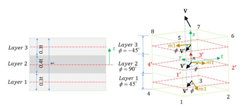
Figure 1.
#RADIOSS STARTER
#---1----|----2----|----3----|----4----|----5----|----6----|----7----|----8----|----9----|---10----|
#-  1. LOCAL_UNIT_SYSTEM:
#---1----|----2----|----3----|----4----|----5----|----6----|----7----|----8----|----9----|---10----|
/UNIT/2
unit for prop
#              MUNIT               LUNIT               TUNIT
                  kg                  mm                  ms
#---1----|----2----|----3----|----4----|----5----|----6----|----7----|----8----|----9----|---10----|
#-  2. GEOMETRICAL SETS:
#---1----|----2----|----3----|----4----|----5----|----6----|----7----|----8----|----9----|---10----|
/PROP/TYPE22/1/2
TSH_COMP example
#   Isolid    Ismstr                         Icstr     Inpts      Iint                            dn
        14         0                           010       333         0                             0
#                q_a                 q_b
                   0                   0
#                 Vx                  Vy                  Vz   skew_ID     Iorth      Ipos
                   1                  -1                   1         0         0         0
#             Ashear
                   0
#              PHI_I               T_I/T                  ZI     MAT_I
                  45                 0.3                   0         1
                  90                 0.4                   0         2
                 -45                 0.3                   0         1
#             dt_min
                   0
#---1----|----2----|----3----|----4----|----5----|----6----|----7----|----8----|----9----|---10----|
#enddata
#---1----|----2----|----3----|----4----|----5----|----6----|----7----|----8----|----9----|---10----|
Comments
- Isolid - Solid formulation
- Isolid =14 formulation (H8 element) must use constant stress formulation (Icstr > 0), which refers to local isoparametric orthogonolized system r-s-t. Definition of the system is described in the comments of /PROP/TYPE6 (SOL_ORTH).
- When using Isolid=15 with pentahedron elements, /PENTA6 elements are recommended but degenerated /BRICK elements can also be used.
- Number of layers.
- For Isolid =
14 formulation (HA8 element), number of layers (
< 9 ) is defined as:
- If Icstr = 001, the number of layers in t direction is equal to k value from Inpts field.
- If Icstr = 010, the number of layers in s direction is equal to j value from Inpts field (Icstr = 010; Inpts = 282; for a number of 8 layers in s direction).
- If Icstr = 100, the number of layers in r direction is equal to i value from Inpts field.
- For Isolid formulation
(HA8 element) when the number of layers > 9 is defined as:
- Use Iint for Isolid
formulation (HA8 element) when the number of layers > 9.
In this case, the thickness direction integration points defined by Inpts should be zero.
Example, Icstr = 010; Inpts = 202; Iint = 100 for a number of 100 layers in "s" direction.
- Use Iint for Isolid
formulation (HA8 element) when the number of layers > 9.
- For Isolid =
14 formulation (HA8 element), number of layers (
< 9 ) is defined as:
- When using the automatic setting option Ismstr = Icpre = Iframe=-1, the values for these options are defined using the best options based on the element formulation, element type, and material. Alternatively, defining Ismstr = Icpre = Iframe=-2 will overwrite the values for these options defined in this property with the best value based on element type and material law. To see the values defined by Radioss, review the “PART ELEMENT/MATERIAL PARAMETER REVIEW” section of the Starter output file.
- Ismstr - Small strain
formulation flag.
- Starting with version 2017, Lagrangian elements whose volume becomes
negative during a simulation will automatically switch strain
formulations to allow the simulation to continue. When this occurs, a
WARNING message will be printed in the Engine output file. The following
options are supported.
Element Type Element Formulation Strain Formulation Negative Volume Handling Method /BRICK Isolid =14, 15 Full geometric nonlinearities Ismstr = 2, 4
Switch to small strain using element shape from cycle before negative volume.
- Starting with version 2017, Lagrangian elements whose volume becomes
negative during a simulation will automatically switch strain
formulations to allow the simulation to continue. When this occurs, a
WARNING message will be printed in the Engine output file. The following
options are supported.
- Othotropy in local
coordinate system.
- The thick shell orthotropy is planar and the third orthotropy direction is coincident with the normal to the shell plane.
- Global vector or skew_ID is used to define the othotropy direction. The global vector or the -axis of specified skew (in this case, global vector is ignored) is projected to the mean plane of soslid element.
- For Isolid=14, the mean plane of the element depends on Icstr.
- r-s for Icstr=001
- r-t for Icstr=010
- s-t for Icstr=001.
- is the angle (in degrees) between the first direction of orthotropy and projection of reference vector on the shell mean plane for layer i.
- Material used for
layer
- Material law type used in Mat_IDi can be different for each layer.
- For Isolid= 15, the material law number defined in /PART will be used to compute the contact interface stiffness and the hourglass stresses.