Solid-Shell Elements

Solid-shell elements form a class of finite element models intermediate between thin shell and conventional solid elements. From geometrical point of view, they are represented by solid meshes with two nodes through the thickness and generally without rotational degree-of-freedom. On the other hand, they account for shell-like behavior in the thickness direction. They are useful for modeling shell-like portions of a 3D structure without the need to connect solid element nodes to shell nodes (Figure 1).


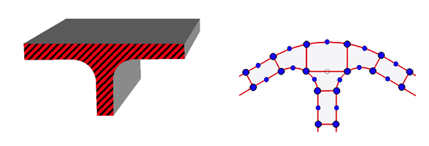
Figure 1. Solid-Shell Elements Application
The derivation of solid-shell elements is more complicated than that of standard solid elements since they are prone to the following problems:
  • Shear and membrane locking with the hybrid strain formulation 1 2, the hybrid stress 3, and the Assumed and Enhanced Natural Strain formulations. 4 5 6 7
  • Trapezoidal locking caused by deviation of mid-plane from rectangular shape 8.
  • Thickness locking due to Poisson's ratio coupling of the in-plane and transverse normal stresses. 1 2 4 6

Solid shell elements in Radioss are the solid elements with a treatment of the normal stresses in the thickness direction. This treatment consists of ensuring constant normal stresses in the thickness by a penalty method. Advantage of this approach with respect to the plane-stress treatment is that it can simulate the normal deformability and exhibits no discernible locking problems. The disadvantage is its possible small time step since it is computed as solid element and the characteristic length is determined often using the thickness.

The solid-shell elements of Radioss are:
  • HA8: 8-node linear solid and solid-shell with or without reduced integration scheme,
  • HSEPH: 8-node linear thick shell with reduced integration scheme and physical stabilization of hourglass modes,
  • PA6: Linear pentahedral element for thick shells,
  • SHELL16: 16-node quadratic thick shell.

The thick shell elements HA8 and HSEPH are respectively the solid elements HA8 and HEPH in which the hypothesis of constant normal stress through the thickness is applied by penalty method. The theoretical features of these elements are explained in Solid Hexahedron Elements. The thick shell element SHELL16 is described hereby.

Thick Shell Elements SHELL16

The element can be used to model thick-walled structures situated between 3D solids and thin shells. The element is presented in Figure 2. It has 16 nodes with three translational DOFs per each node. The element is quadratic in plane and linear through the thickness. The numerical integration through the thickness is carried out by Gauss-Lobatto schemes rise up to 9 integrations to enhance the quality of elasto-plastic behavior. The in-plane integration may be done by a reduced 2x2 scheme or a fully integrated 3x3 points (Figure 3). A reduced integration method is applied to the normal stress in order to avoid locking problems.


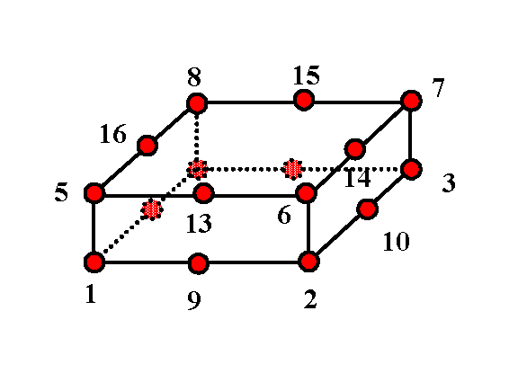
Figure 2. Thick Shell Element SHELL16
The distribution of mass is not homogenous over the nodes. The internal nodes receive three times more mass than the corner nodes as shown in Figure 4.


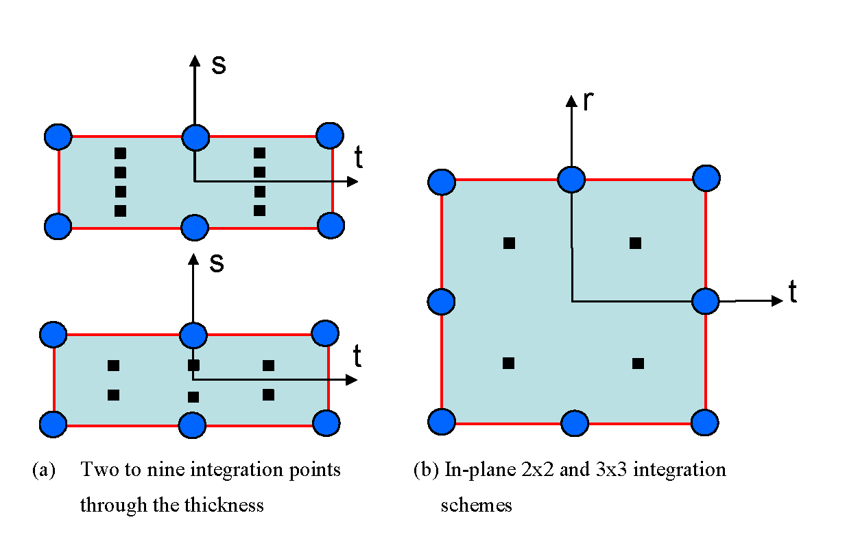
Figure 3. Integration Points for SHELL16


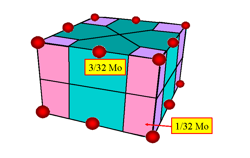
Figure 4. Mass Distribution for SHELL16 Element
1 Ausserer M.F. and Lee S.W., “An eighteen node solid element for thin shell analysis”,Int. Journal Num. Methods in Engineering, Vol. 26, pp. 1345, 1364, 1988.
2 Park H.C., Cho C. and Lee S.W., “An efficient assumed strain element model with six dof per node for geometrically nonlinear shells”, Int. Journal Num. Methods in Engineering, Vol. 38, pp. 4101-4122, 1995.
3 Sze K.Y. and Ghali A., “A hexahedral element for plates, shells and beam by selective scaling”, Int. Journal Num. Methods in Engineering, Vol. 36, pp. 1519-1540, 1993.
4 Betch P. and Stein E., “An assumed strain approach avoiding artificial thickness straining for a nonlinear 4-node shell element”, Computer Methods in Applied Mechanics and Engineering, Vol. 11, pp. 899-909, 1997.
5 Bischoff M. and Ramm E., “Shear deformable shell elements for large strains and rotations”, Int. Journal Num. Methods in Engineering, Vol. 40, pp. 445-452, 1997.
6 Hauptmann R. and Schweizerhof K., “A systematic development of solid-shell element formulations for linear and nonlinear analysis employing only displacement degrees of freedom”, Int. Journal Num. Methods in Engineering, Vol. 42, pp. 49-69, 1988.
7 Simo J.C. and Rifai M.S., “A class of mixed assumed strain methods and the method of incompatible modes”, Int. Journal Num. Methods in Engineering, Vol. 9, pp. 1595-1638, 1990.
8 Donea J., “An Arbitary Lagrangian-Eulerian finite element method for transient dynamic fluid-structure interactions”, Computer methods in applied mechanics, 1982.