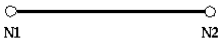
Truss elements are simple two node linear members that only take axial extension or compression.
Figure 1 shows a truss element. Figure 1. Truss Element
Property Input
The only property required by a truss element is the cross-sectional area. This value will change
as the element is deformed. The cross sectional area is computed using:(1)
Where,
Poisson's ratio defined in the material law
Stability
Determining the stability of truss elements is very simple. The characteristic length is defined
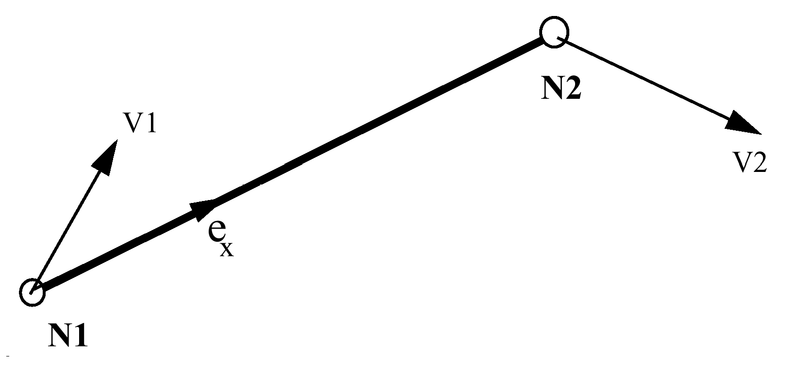
as the length of the element, that is, the distance between N1 and N2 nodes.(2)
Where,
Current truss length
Sound speed
Rigid Body Motion
The rigid body motion of a truss element as shown in Figure 2 shows the different velocities of
nodes 1 and 2. It is the relative velocity difference between the two nodes that produces a
strain in the element, namely ex. Figure 2. Truss Motion
Strain
The strain rate, as shown in Figure 2, is defined as:(3)
Material Type
A truss element may only be assigned two types of material properties. These are TYPE1 and TYPE2,
elastic and elasto-plastic properties, respectively.
Force Calculation
The calculation of forces in a truss element is performed by explicit time
integration:(4)
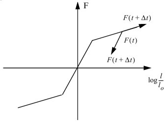
A generalized force-strain graph can be seen in Figure 3. The force rate under elastic
deformation is given by:(5)
Where,
Elastic modulus
Cross-sectional area
In the plastic region, the force rate is given by:(6)
Where,
Gradient of the material curve at the deformation point
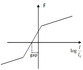
Figure 3. Force-Strain Relationship. (a) without gap; (b) with gap
In a general case, it is possible to introduce a gap distance in the truss definition. If gap is
not null, the truss is activated when the length of the element is equal to the initial
length minus the gap value. This results a force-strain curve shown in Figure 3(b).