Vent Holes

Each vent hole should be represented as a separate component in the same position as in the CAD geometry.

The vent hole is modeled using a void material and property. All nodes of the void vent components should be connected to a fabric component. Density, Young’s modulus and thickness should be defined for the void components using the same values as the fabric material of the airbag. These values are important for the contact defined between void components which helps to maintain the internal airbag volumes.

Material and property for vent void component:
#---1----|----2----|----3----|----4----|----5----|----6----|----7----|----8----|----9----|---10----|
/MAT/VOID/2
Material void
#                RHO                   E
                8E-7                0.38
#---1----|----2----|----3----|----4----|----5----|----6----|----7----|----8----|----9----|---10----|
/PROP/VOID/2
Property void
#              Thick
                 0.3
#---1----|----2----|----3----|----4----|----5----|----6----|----7----|----8----|----9----|---10----|
If an element is referenced in two different vent or porous surface definitions, then the element will be used in the last definition and removed from the first definition (this limitation was removed in 2017.2.3).


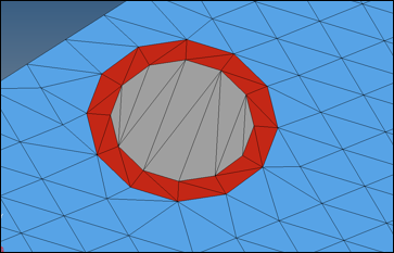
Figure 1. Blue- Airbag Fabric; Grey- Vent Hole; Red - Component That Separates Vent Hole from Rest of Airbag
Definition of isenthalpic vent hole and threshold function to activate the vent hole (kg, mm, ms)
/MONVOL/FVMBAG1
……….
# Sid_vent     Ivent               Avent               Bvent
 666000015         1                   1                   0
#             Tstart               Tstop               dPdef              dtPdef             Idtpdef
                1E30                   0               1E-06                   0                   0
#  fct_IDt   fct_IDP   fct_IDA                       Fscalet             FscaleP             FscaleA
         0       123         0                             0                   0                   0
# fct_IDt'  fct_IDP'  fct_IDA'                      Fscalet'            FscaleP'            FscaleA'
         0         0         0                             0                   0                   0
………


/FUNCT/123
1 vent area scaling function
#                  X                   Y
                  -1                   0
                   0                   0
               1e-06                   0
               2e-06                   1
                   1                   1

The vent hole can be activated at Tstart or when the overpressure defined by Δ P d e f is reached. To use only Tstart define a large Δ P d e f value. To use only Δ P d e f define a large Tstart value. If using Δ P d e f it is recommended to use 1e-06GPa (1% atmospheric pressure).

The Starter outputs a list of elements which belong to each vent hole.
ELEM:    46991 <-> SH3N :   55089506 - VENT HOLE:        1
ELEM:    46992 <-> SH3N :   55089507 - VENT HOLE:        1
ELEM:    46993 <-> SH3N :   55089508 - VENT HOLE:        1
ELEM:    46994 <-> SH3N :   55089509 - VENT HOLE:        1
ELEM:    46995 <-> SH3N :   55089510 - VENT HOLE:        1
ELEM:    46996 <-> SH3N :   55089511 - VENT HOLE:        1
ELEM:    46997 <-> SH3N :   55089512 - VENT HOLE:        1
During the design process, the variation of the vent hole diameter can be simplified by creating several circular components to fill the vent hole area. The vent hole diameter can then be easily modified by changing the parts that define the vent hole surface. When using this method, the vent holes cannot be modeled using VOID properties because not all of the vent hole elements are attached to the airbag fabric. The simplified orthotropic LAW19 can be also used to represent the fabric material of the circular vents but with a reduced stiffness.


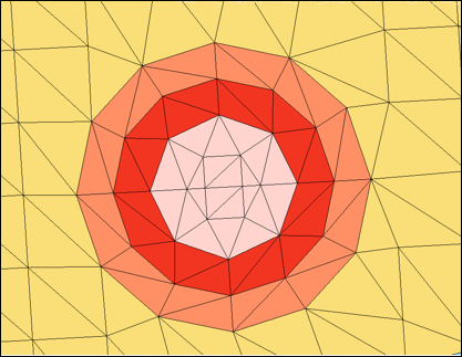
Figure 2. Vent Hole with Variable Diameter
The edges of the slit vent can be connected using stiff springs /PROP/TYPE4 to provide proper folding of the airbag in the area near the slit vent. The springs can also be used to vary the length of the slit vent. Closed edges of the vent should be modeled using stiff springs to avoid opening.


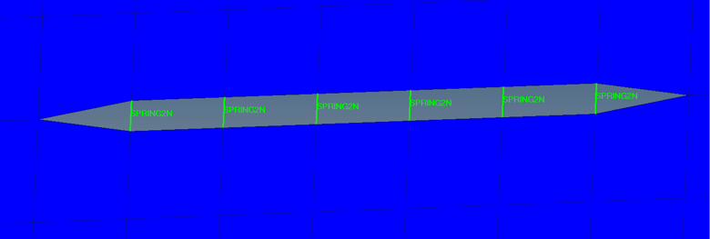
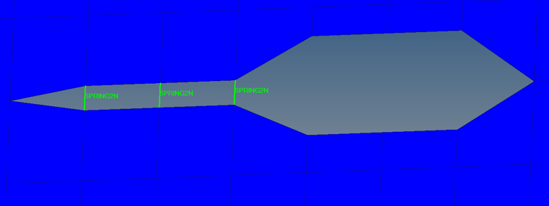
Figure 3. Slit Vent Modeling