Gas Generator

The gas generator model should represent all details available in CAD data: gas generator, injector openings, and retainers.

The gas generator model should represent all the details available in the CAD data: gas generator, injector openings, and retainers. The injector opening is represented by elements on the inflator surface. Inflator components are modeled as shell component with LAW2 material and /RBODY rigid body spider. Mass and inertia properties of inflator components should correspond to hardware.


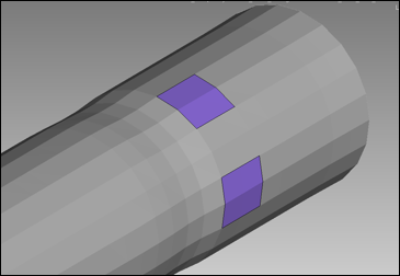
Figure 1. Inflator and Injector Elements

The injection direction is opposite to element's normal. Elements from different injectors should not share common elements. Radioss will assume that the element belongs to the last defined injector. Elements from a vent hole or porous surface also should not share common elements with injectors. Radioss automatically excludes the elements from vent or porous surface definition.

The injector surface can also be defined on an internal surface insideof airbag volume. In this case the gas flow direction is opposite to the internal surface element's normal.

The inflator property /PROP/INJECT1 and /PROP/INJECT2 define the parameters of the injected gas composition. Each of the gas components should be specified as a separate material card: /MAT/GAS/MASS, /MAT/GAS/MOLE, or /MAT/GAS/PREDEF. In the latter case, the gas material is built according to the keyword given in the /MAT/GAS/PREDEF card and units specified in the /BEGIN card.

Example of gas material definition in kg, mm, ms (predefined, related to mass, related to mole):
#---1----|----2----|----3----|----4----|----5----|----6----|----7----|----8----|----9----|---10----|
/MAT/GAS/MASS/1
INJECTOR MIXTURE
#                 MW
              .03300
#                Cpa                 Cpb                 Cpc                 Cpd                 Cpe
             1070.00                   0                   0                   0                   0
#                Cpf
                   0
#---1----|----2----|----3----|----4----|----5----|----6----|----7----|----8----|----9----|---10----|

The molecular weight and coefficients of specific heat coefficient are defined for each of injected gas components.

The heat capacity function.(1)
C p = ( C p a + C p b T + C p c T 2 + C p d T 3 + C p e T 2 + P p f T 4 ) MathType@MTEF@5@5@+= feaagKart1ev2aaatCvAUfeBSjuyZL2yd9gzLbvyNv2CaerbuLwBLn hiov2DGi1BTfMBaeXatLxBI9gBaerbd9wDYLwzYbItLDharqqtubsr 4rNCHbGeaGqiVu0Je9sqqrpepC0xbbL8F4rqqrFfpeea0xe9Lq=Jc9 vqaqpepm0xbba9pwe9Q8fs0=yqaqpepae9pg0FirpepeKkFr0xfr=x fr=xb9adbaqaaeGaciGaaiaabeqaamaabaabaaGcbaGaam4qamaaBa aaleaacaWGWbaabeaakiabg2da9maabmaabaGaam4qamaaBaaaleaa caWGWbGaamyyaaqabaGccqGHRaWkcaWGdbWaaSbaaSqaaiaadchaca WGIbaabeaakiaadsfacqGHRaWkcaWGdbWaaSbaaSqaaiaadchacaWG JbaabeaakiaadsfadaahaaWcbeqaaiaaikdaaaGccqGHRaWkcaWGdb WaaSbaaSqaaiaadchacaWGKbaabeaakiaadsfadaahaaWcbeqaaiaa iodaaaGccqGHRaWkdaWcaaqaaiaadoeadaWgaaWcbaGaamiCaiaadw gaaeqaaaGcbaGaamivamaaCaaaleqabaGaaGOmaaaaaaGccqGHRaWk caWGqbWaaSbaaSqaaiaadchacaWGMbaabeaakiaadsfadaahaaWcbe qaaiaaisdaaaaakiaawIcacaGLPaaaaaa@5830@

should be monotonically increasing for temperatures between ambient temperature and the maximum temperature value given in the temperature curves of the injector. When the function is not monotonically increasing, Radioss automatically corrects the C p ( T ) MathType@MTEF@5@5@+= feaagKart1ev2aaatCvAUfeBSjuyZL2yd9gzLbvyNv2CaerbuLwBLn hiov2DGi1BTfMBaeXatLxBI9gBaerbd9wDYLwzYbItLDharqqtubsr 4rNCHbGeaGqiVu0Je9sqqrpepC0xbbL8F4rqqrFfpeea0xe9Lq=Jc9 vqaqpepm0xbba9pwe9Q8fs0=yqaqpepae9pg0FirpepeKkFr0xfr=x fr=xb9adbaqaaeGaciGaaiaabeqaamaabaabaaGcbaGaam4qamaaBa aaleaacaWGWbaabeaakiaacIcacaWGubGaaiykaaaa@3A1B@ function to keep it monotonic. This can happen when C p e MathType@MTEF@5@5@+= feaagKart1ev2aaatCvAUfeBSjuyZL2yd9gzLbvyNv2CaerbwvMCKf MBHbqefqvATv2CG4uz3bIuV1wyUbqedmvETj2BSbqefm0B1jxALjhi ov2DaebbnrfifHhDYfgasaacH8akY=xipgYlh9vqqj=hEeei0xXdbb a9frFf0=yqFf0dbba91qpepeI8k8fiI+fsY=rqaqpepae9pg0Firpe pesP0xe9Fve9Fve9qapdbaGaaiGadiWaamaaceGaaqaacaqbaaGcba Gaam4qamaaBaaaleaacaWGWbGaamyzaaqabaaaaa@3CA9@ > 0 or one of C p b MathType@MTEF@5@5@+= feaagKart1ev2aaatCvAUfeBSjuyZL2yd9gzLbvyNv2CaerbwvMCKf MBHbqefqvATv2CG4uz3bIuV1wyUbqedmvETj2BSbqefm0B1jxALjhi ov2DaebbnrfifHhDYfgasaacH8akY=xipgYlh9vqqj=hEeei0xXdbb a9frFf0=yqFf0dbba91qpepeI8k8fiI+fsY=rqaqpepae9pg0Firpe pesP0xe9Fve9Fve9qapdbaGaaiGadiWaamaaceGaaqaacaqbaaGcba Gaam4qamaaBaaaleaacaWGWbGaamyzaaqabaaaaa@3CA9@ , C p c MathType@MTEF@5@5@+= feaagKart1ev2aaatCvAUfeBSjuyZL2yd9gzLbvyNv2CaerbwvMCKf MBHbqefqvATv2CG4uz3bIuV1wyUbqedmvETj2BSbqefm0B1jxALjhi ov2DaebbnrfifHhDYfgasaacH8akY=xipgYlh9vqqj=hEeei0xXdbb a9frFf0=yqFf0dbba91qpepeI8k8fiI+fsY=rqaqpepae9pg0Firpe pesP0xe9Fve9Fve9qapdbaGaaiGadiWaamaaceGaaqaacaqbaaGcba Gaam4qamaaBaaaleaacaWGWbGaamyzaaqabaaaaa@3CA9@ , C p d MathType@MTEF@5@5@+= feaagKart1ev2aaatCvAUfeBSjuyZL2yd9gzLbvyNv2CaerbwvMCKf MBHbqefqvATv2CG4uz3bIuV1wyUbqedmvETj2BSbqefm0B1jxALjhi ov2DaebbnrfifHhDYfgasaacH8akY=xipgYlh9vqqj=hEeei0xXdbb a9frFf0=yqFf0dbba91qpepeI8k8fiI+fsY=rqaqpepae9pg0Firpe pesP0xe9Fve9Fve9qapdbaGaaiGadiWaamaaceGaaqaacaqbaaGcba Gaam4qamaaBaaaleaacaWGWbGaamyzaaqabaaaaa@3CA9@ , C p f MathType@MTEF@5@5@+= feaagKart1ev2aaatCvAUfeBSjuyZL2yd9gzLbvyNv2CaerbwvMCKf MBHbqefqvATv2CG4uz3bIuV1wyUbqedmvETj2BSbqefm0B1jxALjhi ov2DaebbnrfifHhDYfgasaacH8akY=xipgYlh9vqqj=hEeei0xXdbb a9frFf0=yqFf0dbba91qpepeI8k8fiI+fsY=rqaqpepae9pg0Firpe pesP0xe9Fve9Fve9qapdbaGaaiGadiWaamaaceGaaqaacaqbaaGcba Gaam4qamaaBaaaleaacaWGWbGaamyzaaqabaaaaa@3CA9@ coefficients are negative.

The composition of the injected gas, injection mass flow and temperature for each of the gas components are defined in the /PROP/INJECT1 or /PROP/INJECT2 cards.

Example of injector property definition:
#---1----|----2----|----3----|----4----|----5----|----6----|----7----|----8----|----9----|---10----|
/PROP/INJECT1/1
Inflator 1
#   Ngases     Iflow            Ascale_T
         5         1                   1
#   mat_ID   fct_IDM   fct_IDT                      Fscale_M            Fscale_T
         1        2         1                              0                   0
#   mat_ID   fct_IDM   fct_IDT                      Fscale_M            Fscale_T
         2        3         1                              0                   0
#   mat_ID   fct_IDM   fct_IDT                      Fscale_M            Fscale_T
         3         4         1                             0                   0
#   mat_ID   fct_IDM   fct_IDT                      Fscale_M            Fscale_T
         4         5         1                             0                   0
#   mat_ID   fct_IDM   fct_IDT                      Fscale_M            Fscale_T
         5         6         1                             0                   0
#---1----|----2----|----3----|----4----|----5----|----6----|----7----|----8----|----9----|---10----|

This card is then referenced in /MONVOL/FVMBAG1 airbag card.

The injector Time to Fire (TTF) should be determined through a sensor in /MONVOL/FVMBAG1, not through a shift of the mass and temperature curves.

When the inflator is determined correctly and referenced in /MONVOL/FVMBAG1, the Radioss Starter outputs the list of elements used as the injector surface.
ELEM:       92 <-> SH3N :   55261587 - INFLATOR :        1
ELEM:      502 <-> SH3N :   55262048 - INFLATOR :        1
ELEM:      622 <-> SH3N :   55261581 - INFLATOR :        1
ELEM:      627 <-> SH3N :   55261568 - INFLATOR :        1
ELEM:      633 <-> SH3N :   55262068 - INFLATOR :        1
ELEM:      814 <-> SH3N :   55261601 - INFLATOR :        1

The inflator model should be validated using a tank test simulation. The tank test report should include the pressure and temperature measured in the test, injector mass flow for each of the gas components, and temperature curves. The pressure and temperature from the test could be compared to the average pressure and temperature in the simulation.