Airbag Housing
The airbag housing should represent all details available in CAD data.
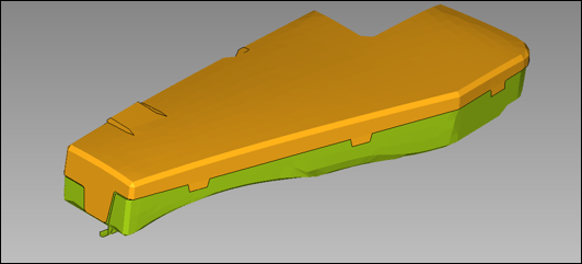
Figure 1. Airbag Housing
When the airbag will be included in a full vehicle simulation, the mesh size and quality should be similar to the full vehicle. Material laws LAW2 and LAW36 can be used to model elasto-plastic materials. Materials with failure should be used to reproduce the opening of the airbag cover.
Solid foam components should be modeled using LAW38 or LAW70, whereas hyperelastic components are modeling using LAW42.
Element properties for shell /PROP/TYPE1 should use Ishell=24 to avoid hourglass effects. For solid foam or hyperelastic components, use /PROP/TYPE14 with Isolid=24 and Ismstr=10.
Contact between Airbag and Environment
- Airbag to inflator
- Airbag to housing
- Airbag to dummy
- Airbag to seat structure
#---1----|----2----|----3----|----4----|----5----|----6----|----7----|----8----|----9----|---10----|
/INTER/TYPE7/666710001
Airbag vs. Housing
#  Slav_id   Mast_id      Istf      Ithe      Igap                Ibag      Idel     Icurv      Iadm
 666100103 666200201         4         0         0                   1         2         0         0
#         Fscale_GAP             GAP_MAX             Fpenmax
                   0                   0                   0
#              STMIN               STMAX          %MESH_SIZE               dtmin
                   1                1E30                   0                   0
#              STFAC                FRIC             GAP_MIN              Tstart               Tstop
                   1                  .1                   1                   0                   0
#     I_BC                        INACTI               VIS_S               VIS_F              BUMULT
       000                             6                   0                   0                   0
#    Ifric    Ifiltr               Xfreq     Iform
         0         0                   0         2
#---1----|----2----|----3----|----4----|----5----|----6----|----7----|----8----|----9----|---10----|
/INTER/TYPE7/666710002
Housing vs. Airbag
#  Slav_id   Mast_id      Istf      Ithe      Igap                Ibag      Idel     Icurv      Iadm
 666100104 666200202         4         0         0                   1         2         0         0
#         Fscale_GAP             GAP_MAX             Fpenmax
                   0                   0                   0
#              STMIN               STMAX          %MESH_SIZE               dtmin
                   1                1E30                   0                   0
#              STFAC                FRIC             GAP_MIN              Tstart               Tstop
                   1                  .1                   1                   0                   0
#     I_BC                        INACTI               VIS_S               VIS_F              BUMULT
       000                             6                   0                   0                   0
#    Ifric    Ifiltr               Xfreq     Iform
         0         0                   0         2
#---1----|----2----|----3----|----4----|----5----|----6----|----7----|----8----|----9----|---10----|
/INTER/TYPE11/666810001
Airbag vs. Housing
#  Slav_id   Mast_id     I_stf               I_gap   Multimp                Idel
 666100102 666200203         4                   0         0                   2
#              STmin               STmax           MESH_SIZE               dtmin     Iform   Sens_Id
                   1                   0                   0                   0         2         0
#              STFAC                FRIC                 GAP              Tstart               Tstop
                   1                   0                 0.9                   0                   0
#     I_BC                        INACTI               VIS_S               VIS_F              BUMULT
       000                             6                   0                   0                   0
#---1----|----2----|----3----|----4----|----5----|----6----|----7----|----8----|----9----|---10----|- Istf=4, to provide proper contact stiffness
- Ibag=1, for vent closure
- Idel=2, to remove deleted elements from contact
- Stmin=1KN/mm
- Iform=2
Time History and Animation Output
- Global gas dynamic parameters: mass of gas, volume of airbag, area of airbag, pressure (average), temperature (average) and heat capacity coefficients (average).
- For each vent hole: vent area, outflow velocity, and outflow mass. (Default starting in 2017.2.3)
- Finite volume parameters: number of Finite Volumes (NFV) and smallest Finite Volume time step (DTBAG). For versions before 2017.2.4, the NFV and DTBAG options were not included in the default output and thus have to be defined when using older versions.
#---1----|----2----|----3----|----4----|----5----|----6----|----7----|----8----|----9----|---10----|
/TH/MONV/666000001
Airbag MonVol Time History - 666
#     var1      var2      var3      var4      var5      var6      var7      var8      var9     var10
DEF       NFV       DTBAG
#     Obj1      Obj2      Obj3      Obj4      Obj5      Obj6      Obj7      Obj8      Obj9     Obj10
 666000001
#---1----|----2----|----3----|----4----|----5----|----6----|----7----|----8----|----9----|---10----|
The local pressure should be measured in the model by creating a pressure /GAUGE using a node of the airbag fabric where the pressure was measured near the injector in the test.
#---1----|----2----|----3----|----4----|----5----|----6----|----7----|----8----|----9----|---10----|
/GAUGE/1
FWD
#  node_ID                                          shell_ID                DIST
  50050421
#---1----|----2----|----3----|----4----|----5----|----6----|----7----|----8----|----9----|---10----|
/TH/GAUGE/1
TH GAUGE
#     var1      var2      var3      var4      var5      var6      var7      var8      var9     var10
DEF
#     Obj1      Obj2      Obj3      Obj4      Obj5      Obj6      Obj7      Obj8      Obj9     Obj10
         1
#---1----|----2----|----3----|----4----|----5----|----6----|----7----|----8----|----9----|---10----|
The mass flow through any permeable internal airbag surfaces can be output using the /TH/SURF card.
#---1----|----2----|----3----|----4----|----5----|----6----|----7----|----8----|----9----|---10----|
/TH/SURF/666000002
Airbag MonVol Time History - 666
#     var1      var2      var3      var4      var5      var6      var7      var8      var9     var10
AREA      MASSFLOW
#     Obj1      Obj2      Obj3      Obj4      Obj5      Obj6      Obj7      Obj8      Obj9     Obj10
 666000001
#---1----|----2----|----3----|----4----|----5----|----6----|----7----|----8----|----9----|---10----|
The card should refer to surfaces defined by /SURF.
- /ANIM/NODA/P or /H3D/NODA/P
- /ANIM/NODA/DENS or /H3D/NODA/DENS
- /ANIM/NODA/TEMP or /H3D/NODA/TEMP
- /ANIM/VECT/FVEL or /H3D/NODA/FVEL
Time Step and Merging Control
The time step and number of finite volumes influence the run time of the airbag simulation model. This section describes the options available to influence the time step and number of finite volumes.
- Time step scale factor entered in /DT/FVMBAG/1
- Characteristic length which is the minimum edge length of the initial finite volume tetra mesh
- Maximum gas velocity
- Maximum sonic velocity
NUMBER
                    OF ADDITIONAL BRICKS
” is for automatic mesh generation,
Kmesh=2 or if the finite volume elements are
created manually in HyperMesh.FVMBAG: FINITE VOLUME MINIMUM LENGTH
-------------------------------------
VOLUME NUMBER 666000001
TOTAL NUMBER OF FINITE VOLUMES.. . . . . . .= 30610
NUMBER OF POLYHEDRA . . . . .. . . . . . . .= 0
MINIMUM LENGTH USED FOR TIME STEP. . . .= 0.000000000000
MINIMUM LENGTH BASED ON VOLUME . . . . .= 10000000000.00
MINIMUM LENGTH BASED ON NODAL DISTANCE .= 1.0000000000000E+15
NUMBER OF ADDITIONAL BRICKS. . . . . . . . .= 30610
MINIMUM LENGTH BASED ON VOLUME . . . . .= 0.7039415515349
MINIMUM LENGTH BASED ON NODAL DISTANCE .= 0.5268862297298
MINIMUM LENGTH BASED ON VOLUME/AREA. . .= 4.9347603553545E-02
Since there is no gas motion, the initial time step is the characteristic length divided by sonic velocity of air at a room temperature. As the injection starts, the gas velocity and gas sonic velocities increase and the time step normally drops during a short phase after the time to fire. In this phase the time step may become less than the target structural time step and thus control the time step of the run. However, after some time (normally 5-10ms) the gas velocity is decreasing and the time step and becomes higher than the structural time step. It is important to minimize the length of time that the airbag time step is the lowest time step in the simulation.
The characteristic length is underestimated in the simulation because it is based on the minimum edge length of the folded airbag. Thus, the time step can be increased by making a value greater than 1 in /DT/FVMBAG/1.
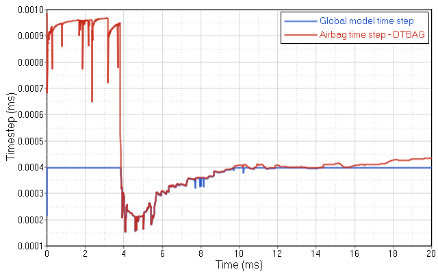
Figure 2. Typical Time Step Evolution for a Model with FVM Airbag (red is the global time step, blue is the FVM time step) . FVM airbag is controlling the time step from 3.75ms to 7.5ms)
- Stability merging: this is default merging. A FV is always merged when its volume becomes negative.
- Global merging: a FV is merged if its volume becomes less than factor Cgmerg multiplied by the average volume of all the finite volumes which is the airbag volume divided by the number of FVs. The parameter is normally specified in /FVMBAG/MODIF.
- Neighborhood merging: a FV is merged if its volume becomes less than Cnmerg multiplied by the average volume of its neighbor finite volumes. The parameter is normally specified in /FVMBAG/MODIF card. This type of merging is difficult to control and therefore it is not recommended.
- Time step merging: a FV is merged if its time step < dtmin defined in /DT/FVMBAG/1
The number of finite volumes reduces quickly during a simulation. However, it is important to have a smooth reduction of number of finite volumes and a sufficient number (1-10% of the initial number) of finite volumes at the end of simulation. The easiest way to control the merging of finite volume is to adjust the /FVMBAG/MODIF Cgmerg option. Normally the value should be between 0.01 and 0.1.
** FINITE VOLUME        24 MERGE STATISTICS **
 NUMBER OF REMAINING FINITE VOLUMES .....:      6999
 GLOBAL MERGE ...........................:     22730
 NEIGHBORHOOD MERGE .....................:         0
 STABILITY MERGE ........................:       885
 TIME STEP MERGE ........................:         2
Switch from FVM to Uniform Pressure (UP) Approach
The /MONVOL/FVMBAG1 Tswitch parameter can be used to switch from a FVM to UP calculation. The UP calculation is less costly and thus saves simulation time. The switch should be performed at a time point when pressure inside of airbag stabilize which occurs when the locally measured pressure becomes the same as the average pressure.