Finite Volume Method Airbag Modeling
In Radioss the standard method for airbag calculation is the Finite Volume Method (FVM).
The FVM models gas flow inside the airbag, including the interaction with internal airbag components which could include internal walls, baffles, etc. The airbag card, /MONVOL/FVMBAG1 is used to set up the FVM airbag. Uniform pressure airbags can be used for debugging purposes to check unfolding, contacts, and global consistency of gas dynamic parameters. /MONVOL/AIRBAG1 can be used to activate a uniform pressure airbag for debugging.
#---1----|----2----|----3----|----4----|----5----|----6----|----7----|----8----|----9----|---10----|
/MONVOL/FVMBAG1/1
SAB
#     Isur
         4
#           Ascale_T            Ascale_P            Ascale_S            Ascale_A            Ascale_D
                   0                   0                   0                   0                   0
#   mat_ID                                              Pext                 T_0     Iequi      Ittf
      5000                                         1.0135E-4                 296                   3
#     Njet
         1
#inject_ID   sens_IDsurf_IDinj
     10001        22        19
#fct_IDvel                    Fscale_vel
         4                             0
#    Nvent
         0
#   Iframe       Kmesh           Tswicth
         0          2                40
#                 l1                  l2                  l3

#      Nb1       Nb2       Nb3 grbric_ID surf_IDin      Iref
         0         0         0         0        20         0
#   Igmerg                        Cgmerg              Cnmerg               Ptole
         0                         1e-04               1e-04                   0
#                 qa                  qb                Hmin
                                                           0
#   Ilvout    Nlayer   Nfacmax    Nppmax    ifvani
         0         0         0         0         1
/SURF/PART/4
AIRBAG EXTERNAL SURFACE
         1         2         4         5         6         7
/SURF/PART/19
INJECTOR SURFACE
         5
/SURF/PART/20
INJECTOR SURFACE
         5
/GRBRIC/PART/21
TETRA4
         8
#---1----|----2----|----3----|----4----|----5----|----6----|----7----|----8----|----9----|---10----|
The closed airbag external surface should be defined using /SURF/PART and reference a set of shell components with normals directed outwards.
The scaling parameters, Ascale_T, Ascale_P, Ascale_S, Ascale_A, and Ascale_D are not used.
Atmospheric values are defined for initial air material, initial temperature, and initial pressure.
The parameter, Ittf should be set to 3. In this case, vents are activated at TTF of the first injector given in the sensor referenced in /MONVOL/FVMBAG1 and all time dependent parameters and curves controlling vent openings and porosities will be shifted by the sense activation time of the first injector
The number of injectors is specified by the Njet flag. Elements used as an injection surface should be place into separate PART component, which belongs either to the external or internal airbag surface. Different injectors cannot use same elements for injector surfaces.
Time to fire (TTF) to start gas injection should be defined in /SENSOR. Global parameter definition /PARAMETER can be used to parametrize input of the TTF and other airbag parameters.
The function for injection velocity should be set at a constant value of approximately the velocity of sound of injected gas. This function does not have significant impact to simulation results.
Option Iequil=1 should be used. The option provides a simplified FVM cycling before TTF.
The function for injection velocity should be set at a constant value of approximately the velocity of sound of injected gas. This function does not have significant impact to simulation results.
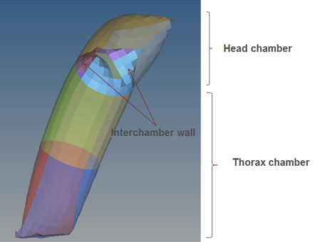
Figure 1. Simple sleeve Airbag with 2 chambers
The Initial Finite Volume mesh is created automatically when the option /MONVOL/FVMBAG1 Kmesh=2 is used and no manually created initial tetra Finite Volume mesh is defined as described in the next section. Next, the airbag is checked to make sure no intersections exist in the airbag external and internal surfaces. If no intersections exist, the Finite Volume mesh is created. If the Finite Volume mesh cannot be created due to intersections in the airbag components, an error message is written with the possible node/element numbers and positions that are causing the problem with creation of Finite Volume mesh. When this happens, HyperMesh can be used to inspect and correct the issues with the airbag mesh. Use the check 2Dmesh option in the tetramesh panel, with default setting to see if the external and internal airbag components are acceptable for tetra mesh generation.
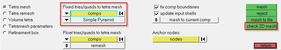
Figure 2.
The initial Finite Volume mesh /TETRA4 elements should be place into a separate /PART and assigned the material /MAT/VOID and property /PROP/VOID. The mesh must completely fill the airbag volume.
#---1----|----2----|----3----|----4----|----5----|----6----|----7----|----8----|----9----|---10----|
/PART/8
TETRA4
          8         8         0
/MAT/VOID/8
tetra
/PROP/VOID/8
tetra
#---1----|----2----|----3----|----4----|----5----|----6----|----7----|----8----|----9----|---10----|
INITIAL VOLUME OF MONITORED VOLUME. . .= 299199.9998912

VOLUME NUMBER          1
NUMBER OF SURFACE POLYGONS. . . . . . .=      1200
NUMBER OF SURFACE TRIANGLES . . . . . .=      1200
NUMBER OF COMMUNICATION POLYGONS. . . .=      2536
NUMBER OF COMMUNICATION TRIANGLES . . .=      2536
NUMBER OF FINITE VOLUMES. . . . . . . .=      1568
MIN FINITE VOLUME VOLUME. . . . . . . .=  66.66666700000         (FINITE VOLUME ID 292)
INITIAL MERGING VOLUME. . . . . . . . .=  19.08163264612
SUM VOLUME OF FINITE VOLUMES. . . . . .= 299199.9998912
SUM AREA SURFACE TRIANGLES. . . . . . .=  230031.1439046
SUM MASS OF FINITE VOLUMES. . . . . . .= 3.9428379122204E-04
WARNING ID :          631
** WARNING IN FVMBAG DEFINITION
DESCRIPTION :
-- MONITORED VOLUME ID : 1
-- MONITORED VOLUME TITLE : SAB
IN LOCAL FRAME DIRECTION 1
GIVEN LENGTH 0.000000000000 IS SMALLER THAN BOUNDING LENGTH 301.4996942325
IT IS RESET TO 304.5146911748
WARNING ID :          631
** WARNING IN FVMBAG DEFINITION
DESCRIPTION :
-- MONITORED VOLUME ID : 1
-- MONITORED VOLUME TITLE : SAB
IN LOCAL FRAME DIRECTION 2
GIVEN LENGTH 0.000000000000 IS SMALLER THAN BOUNDING LENGTH 100.0000000000
IT IS RESET TO 101.0000000000
WARNING ID :          631
** WARNING IN FVMBAG DEFINITION
DESCRIPTION :
-- MONITORED VOLUME ID : 1
-- MONITORED VOLUME TITLE : SAB
IN LOCAL FRAME DIRECTION 3
GIVEN LENGTH 0.000000000000 IS SMALLER THAN BOUNDING LENGTH 1.535460483274
IT IS RESET TO 1.550815088107
The quality of tetra mesh is not important because the finite volumes based on the tetra mesh will be merged according to the strategy provided by the merging parameters. , , and can be entered in /MONVOL/FVMBAG1. However, it is recommended to deactivate the merging process during Starter initialization by setting = =1e-04 and use an advanced merging algorithm in the Engine, where the same parameters can be defined in /FVMBAG/MODIF or /DT/FVMBAG/Iflag.
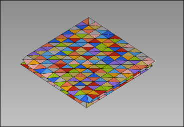
Figure 3. Representation of Initial Finite Volumes in *A000 File
The number of tetra elements depends on the complexity and the type of airbag. For example, a side airbag can be about 30,000 – 50,000 tetras, and a curtain airbag 250,000 – 500,000 tetras.
The automatic volume meshing option /MONVOL/FVMBAG1 Kmesh=1, should not be used. It is recommended to either use Kmesh=2 or manually create the tetramesh in HyperMesh.