Reference Geometry
The reference geometry definition consists of the undeformed element size for all the elements in the airbag. When reference geometry is used, no stress occurs in the material until the element is the same size as its reference size.
There are two situations where reference geometry should be used. First, during folding, the airbag elements can become distorted where the length of the inner and outer elements of a fold will not be the same. Thus, when the airbag inflates the reference geometry is used to prevent any stress in the element until the element reaches it reference size.
The second reason the airbag elements can be smaller is when the airbag is scaled down to be put into a canister. In this case, the airbag does not have to be folded, but the deployment behavior will not match a folded airbag. Thus, scaling the unfolded airbag down to fit into the canistor is not recommended.
The position of the reference geometry is not important, only the relative distances between the nodes. The fabric orientation (material orthtropy) is defined using the reference gemetry since this is easier than using the folded airbag.
There are three ways to define reference geometry.
/EREF
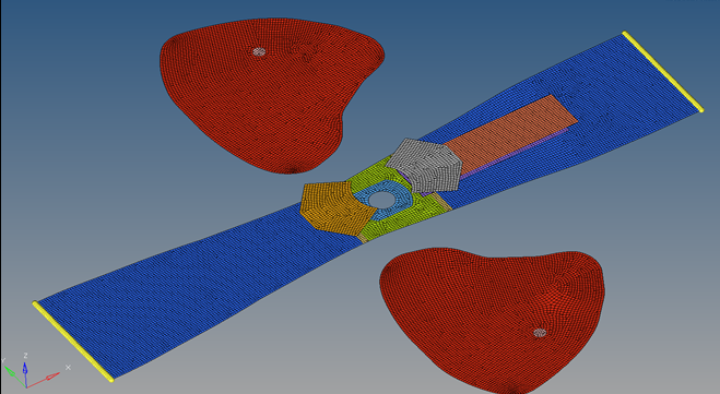
Figure 1. Flat Reference Geometry for a Passenger Airbag
/XREF
This method lists reference geometry using the node ID and reference coordinates. The node IDs must match the node ID listed in the assembled (folded) airbag. One /XREF is created per part. If the reference geometry parts of the airbag are not connected as shown in Figure 1, then the same nodes are listed in multiple /XREF in areas where the parts connect. This method is not as flexible as /EREF due to the requirement of the node ID matching the assembled (folded) airbag.
/REFSTA
In this case, the reference geometry node positions are read from a separate file which contains the reference coordinates of the nodes using the same format as the /NODE option. This method only works for closed reference geometry volumes and thus is not recommended.
Compatibility
Reference geometry can be used with shells using law /MAT/LAW1 (ELAST), /MAT/LAW19 (FABRI) or /MAT/LAW58 (FABR_A). When used with shells, ZeroStress=1 should be defined in /MAT/LAW19 (FABRI) or /MAT/LAW58 (FABR_A) to prevent any stress or movement in the airbag before the time to fire.