/MAT/LAW113 (SPR_BEAM)
Block Format Keyword This beam type spring material works as a beam element with six independent modes of deformation. This spring accounts for nonlinear stiffness, damping and different unloading.
Deformation, force, and energy-based failure criteria are available. This material must be assigned to a /PART that references the spring property /PROP/TYPE23 (SPR_MAT).
Format
| (1) | (2) | (3) | (4) | (5) | (6) | (7) | (8) | (9) | (10) |
|---|---|---|---|---|---|---|---|---|---|
| /MAT/LAW113/mat_ID/unit_ID or /MAT/SPR_BEAM/mat_ID/unit_ID | |||||||||
| mat_title | |||||||||
| Ifail | Ileng | Ifail2 | |||||||
| (1) | (2) | (3) | (4) | (5) | (6) | (7) | (8) | (9) | (10) |
|---|---|---|---|---|---|---|---|---|---|
| K1 | C1 | A1 | B1 | D1 | |||||
| fct_ID11 | H1 | fct_ID21 | fct_ID31 | fct_ID41 | |||||
| F1 | E1 | Ascale1 | Hscale1 | ||||||
| (1) | (2) | (3) | (4) | (5) | (6) | (7) | (8) | (9) | (10) |
|---|---|---|---|---|---|---|---|---|---|
| K2 | C2 | A2 | B2 | D2 | |||||
| fct_ID12 | H2 | fct_ID22 | fct_ID32 | fct_ID42 | |||||
| F2 | E2 | Ascale2 | Hscale2 | ||||||
| (1) | (2) | (3) | (4) | (5) | (6) | (7) | (8) | (9) | (10) |
|---|---|---|---|---|---|---|---|---|---|
| K3 | C3 | A3 | B3 | D3 | |||||
| fct_ID13 | H3 | fct_ID23 | fct_ID33 | fct_ID43 | |||||
| F3 | E3 | Ascale3 | Hscale3 | ||||||
| (1) | (2) | (3) | (4) | (5) | (6) | (7) | (8) | (9) | (10) |
|---|---|---|---|---|---|---|---|---|---|
| K4 | C4 | A4 | B4 | D4 | |||||
| fct_ID14 | H4 | fct_ID24 | fct_ID34 | fct_ID44 | |||||
| F4 | E4 | Ascale4 | Hscale4 | ||||||
| (1) | (2) | (3) | (4) | (5) | (6) | (7) | (8) | (9) | (10) |
|---|---|---|---|---|---|---|---|---|---|
| K5 | C5 | A5 | B5 | D5 | |||||
| fct_ID15 | H5 | fct_ID25 | fct_ID35 | fct_ID45 | |||||
| F5 | E5 | Ascale5 | Hscale5 | ||||||
| (1) | (2) | (3) | (4) | (5) | (6) | (7) | (8) | (9) | (10) |
|---|---|---|---|---|---|---|---|---|---|
| K6 | C6 | A6 | B6 | D6 | |||||
| fct_ID16 | H6 | fct_ID26 | fct_ID36 | fct_ID46 | |||||
| F6 | E6 | Ascale6 | Hscale6 | ||||||
| (1) | (2) | (3) | (4) | (5) | (6) | (7) | (8) | (9) | (10) |
|---|---|---|---|---|---|---|---|---|---|
| Fcut | Fsmooth | ||||||||
| c1 | n1 | ||||||||
| c2 | n2 | ||||||||
| c3 | n3 | ||||||||
| c4 | n4 | ||||||||
| c5 | n5 | ||||||||
| c6 | n6 | ||||||||
Definitions
| Field | Contents | SI Unit Example |
|---|---|---|
| mat_ID | Material
identifier. (Integer, maximum 10 digits) |
|
| unit_ID | Unit Identifier. (Integer, maximum 10 digits) |
|
| mat_title | Material
title. (Character, maximum 100 characters) |
|
| Density. (Real) |
||
| Ifail | Failure criteria.
(Integer) |
|
| Ileng | Input per unit length
flag. 4
5
(Integer) |
|
| Ifail2 | Failure model flag.
(Integer) |
|
| Ki | If
fct_ID1i =
0: Linear loading and unloading stiffness. If fct_ID1i ≠ 0: Only used as unloading stiffness for elasto-plastic springs. = 1, 2, 3 are translation DOF. = 4, 5, 6 are rotation DOF. (Real) |
if
= 1, 2, 3 if = 4, 5, 6 |
| Ci | Damping. = 1, 2, 3 are translation DOF. = 4, 5, 6 are rotation DOF. (Real) |
if
= 1, 2, 3 if = 4, 5, 6 |
| Ai | Nonlinear stiffness
function scale factor. = 1, 2, 3 are translation DOF. = 4, 5, 6 are rotation DOF. Default = 1.0 (Real) |
if
= 1, 2, 3 if = 4, 5, 6 |
| Bi | Scale factor for
logarithmic rate effects. = 1, 2, 3 are translation DOF. = 4, 5, 6 are rotation DOF. Default = 0.0 (Real) |
if
= 1, 2, 3 if = 4, 5, 6 |
| Di | Scale factor for
logarithmic rate effects. = 1, 2, 3 are translation DOF. = 4, 5, 6 are rotation DOF. Default = 1.0 (Real) |
if
= 1, 2, 3 if = 4, 5, 6 |
| fct_ID1i | Function identifier
defining nonlinear stiffness
.
If Hi =4: Function defines upper yield curve. If Hi =8: Function is mandatory and defines the force or moment vs spring length. = 1, 2, 3 are translation DOF. = 4, 5, 6 are rotation DOF. (Integer) |
|
| Hi | Spring Hardening flag for
nonlinear spring.
= 1, 2, 3 are translation DOF. = 4, 5, 6 are rotation DOF. (Integer) |
|
| fct_ID2i | Function identifier
defining force or moment as a function of spring velocity,
. = 1, 2, 3 are translation DOF. = 4, 5, 6 are rotation DOF. (Integer) |
|
| fct_ID3i | Function identifier. If Hi =4: Defines lower yield curve. If Hi =5: Defines residual displacement or rotation vs maximum displacement or rotation. If Hi =6: Defines nonlinear unloading curve. If Hi =7: Defines nonlinear unloading curve. = 1, 2, 3 are translation DOF. = 4, 5, 6 are rotation DOF. (Integer) |
|
| fct_ID4i | Function identifier for
nonlinear damping,
. = 1, 2, 3 are translation DOF. = 4, 5, 6 are rotation DOF. (Integer) |
|
| Negative translation
failure limit. = 1, 2, 3 are translation DOF. Default = -1030 (Real) |
||
| If Ifail2 = 0 or 1: Failure displacement. | ||
| If Ifail2 = 2: Failure force. | ||
| If Ifail2 = 3: Failure internal energy. | ||
| Negative rotational
failure limit. = 4, 5, 6 are rotation DOF. Default = -1030 (Real) |
||
| If Ifail2 = 0 or 1: Failure rotation. | ||
| If Ifail2 = 2: Failure moment. | ||
| If Ifail2 = 3: Failure internal energy. | ||
| Positive translation
failure limit. = 1, 2, 3 are translation DOF. Default = -1030 (Real) |
||
| If Ifail2 = 0 or 1: Failure displacement. | ||
| If Ifail2 = 2: Failure force. | ||
| If Ifail2 = 3: Failure internal energy. | ||
| Positive rotational
failure limit. = 4, 5, 6 are rotation DOF. Default = -1030 (Real) |
||
| If Ifail2 = 0 or 1: Failure rotation. | ||
| If Ifail2 = 2: Failure moment. | ||
| If Ifail2 = 3: Failure internal energy. | ||
| Fi | Abscissa scale factor for
the damping functions for the
and
. = 1, 2, 3 are translation DOF. = 4, 5, 6 are rotation DOF. Default = 1.0 (Real) |
if
= 1, 2, 3 if = 4, 5, 6 |
| Ei | Ordinate scale factor for
the damping function
. = 1, 2, 3 are translation DOF. = 4, 5, 6 are rotation DOF. (Real) |
if
= 1, 2, 3 if = 4, 5, 6 |
| Ascalei | Abscissa scale factor for
the stiffness function
. = 1, 2, 3 are translation DOF. = 4, 5, 6 are rotation DOF. Default = 1.0 (Real) |
if
= 1, 2, 3 if = 4, 5, 6 |
| Hscalei | Ordinate scale factor for
the damping function
. = 1, 2, 3 are translation DOF. = 4, 5, 6 are rotation DOF. Default = 1.0 (Real) |
if
= 1, 2, 3 if = 4, 5, 6 |
| Reference translational
velocity. Default = 1.0 (Real) |
||
| Reference rotational
velocity. Default = 1.0 (Real) |
||
| Fcut | Strain rate cutting
frequency. Default = 1030 (Real) |
|
| Fsmooth | Smooth strain rate flag.
(Integer) |
|
| ci | Relative velocity coefficient. = 1, 2, 3 are translation DOF. = 4, 5, 6 are rotation DOF. Default = 0.0 (Real) |
|
| If Ifail2 = 0 or 1: Failure displacement or rotation. |
if
= 1, 2, 3 if = 4, 5, 6 |
|
| If Ifail2 = 2: Failure force or moment. |
if
= 1, 2, 3 if = 4, 5, 6 |
|
| If Ifail2 = 3: Coefficient for failure internal energy. | ||
| ni | Relative velocity exponent. = 1, 2, 3 are translation DOF. = 4, 5, 6 are rotation DOF. Default = 0.0 (Real) |
|
| Failure scale factor. = 1, 2, 3 are translation DOF. = 4, 5, 6 are rotation DOF. Default = 1.0 (Real) |
||
| Exponent. = 1, 2, 3 are translation DOF. = 4, 5, 6 are rotation DOF. Default = 2.0 (Real) |
Example
#RADIOSS STARTER
#---1----|----2----|----3----|----4----|----5----|----6----|----7----|----8----|----9----|---10----|
#-  1. LOCAL_UNIT_SYSTEM:
#---1----|----2----|----3----|----4----|----5----|----6----|----7----|----8----|----9----|---10----|
/UNIT/2
units for material and property
                  Mg                  mm                   s
#---1----|----2----|----3----|----4----|----5----|----6----|----7----|----8----|----9----|---10----|
/PROP/SPR_MAT/26/2
SPOTWELD_NO_RUPTURE
#    Imass                        Volume             Inertia   skew_ID   sens_ID    Isflag
         2                             1             6.55E-6         0         0         0
/MAT/LAW113/26/2
SPOTWELD_NO_RUPTURE
                2E-6
#    Ifail     Ileng    Ifail2

#                 K1                  C1                  A1                  B1                  D1
              100000                   0                   0                   0                   0
# fct_ID11        H1  fct_ID21  fct_ID31  fct_ID41                    delta_min1          delta_max1
         1         1         0         0         0                             0               .5E-1
#                 F1                  E1             Ascale1             Hscale1
                   0                   0                   0                   0
#                 K2                  C2                  A2                  B2                  D2
              500000                   0                   0                   0                   0
# fct_ID12        H2  fct_ID22  fct_ID32  fct_ID42                    delta_min2          delta_max2
         2         1         0         0         0                        -.5E-1               .5E-1
#                 F2                  E2             Ascale2             Hscale2
                   0                   0                   0                   0
#                 K3                  C3                  A3                  B3                  D3
              500000                   0                   0                   0                   0
# fct_ID13        H3  fct_ID23  fct_ID33  fct_ID43                    delta_min3          delta_max3
         2         1         0         0         0                        -.5E-2               .5E-2
#                 F3                  E3             Ascale3             Hscale3
                   0                   0                   0                   0
#                 K4                  C4                  A4                  B4                  D4
             5000000                   0                   0                   0                   0
# fct_ID14        H4  fct_ID24  fct_ID34  fct_ID44                    delta_min4          delta_max4
         0         1         0         0         0                         -.015                .015
#                 F4                  E4             Ascale4             Hscale4
                   0                   0                   0                   0
#                 K5                  C5                  A5                  B5                  D5
             5000000                   0                   0                   0                   0
# fct_ID15        H5  fct_ID25  fct_ID35  fct_ID45                    delta_min5          delta_max5
         0         1         0         0         0                         -.015                .015
#                 F5                  E5             Ascale5             Hscale5
                   0                   0                   0                   0
#                 K6                  C6                  A6                  B6                  D6
             5000000                   0                   0                   0                   0
# fct_ID16        H6  fct_ID26  fct_ID36  fct_ID46                    delta_min6          delta_max6
         0         1         0         0         0                         -.015                .015
#                 F6                  E6             Ascale6             Hscale6
                   0                   0                   0                   0
#                 V0              Omega0               F_cut   Fsmooth
                   0                   0                   0         0
#                  C                   n               alpha                beta
                   0                   0                   0                   0
                   0                   0                   0                   0
                   0                   0                   0                   0
                   0                   0                   0                   0
                   0                   0                   0                   0
                   0                   0                   0                   0
#---1----|----2----|----3----|----4----|----5----|----6----|----7----|----8----|----9----|---10----|
#-  7. FUNCTIONS:
#---1----|----2----|----3----|----4----|----5----|----6----|----7----|----8----|----9----|---10----|
/FUNCT/1
spotweld tensile function
#                  X                   Y
              -250.0             -8250.0
               -0.25             -8250.0
                 0.0                 0.0
                0.25              8250.0
               250.0              8250.0
#---1----|----2----|----3----|----4----|----5----|----6----|----7----|----8----|----9----|---10----|
/FUNCT/2
Spotweld shear function
#                  X                   Y
              -250.0            -25000.0
               -0.25            -25000.0
                 0.0                 0.0
                0.25             25000.0
               250.0             25000.0
#enddata
Comments
- When used with /PROP/TYPE23 (SPR_MAT), this material law has the same behavior as spring property /PROP/SPR_BEAM.
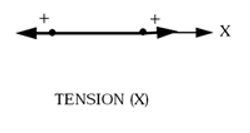
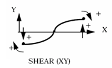
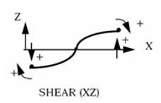
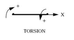
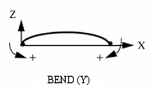
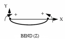
- Inputs repeated for
each degree of freedom (DOF)
are defined with the following directions:
- =1: tension/compression
- =2: shear xy
- =3: shear xz
- =4: torsion
- =5: bending y
- =6: bending z
- The spring's
direction is defined using nodes N1 and N2 of
the spring.If the node of the spring N3 is defined, the spring's direction is defined using nodes N1 and N3 of the spring. N3, N2, and N1 should not be in a line.
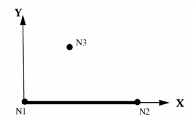
Figure 1.- The
direction is:
(1) - If node N3 is not defined in the element input, and skew system is
defined in the /PROP/TYPE23 (SPR_MAT) input, the
direction is:
(2) - If neither node N3 nor skew system are defined in input, the
direction is:
(3)
(4) Finally, direction is found as:(5) - The
direction is:
- If Ileng = 1, the spring
stiffness properties are related on the initial spring length. The input should
be entered as:Each spring will then have the following properties in the model:
- and
- Spring values entered in the spring property fields
- and
- Spring’s actual physical mass, inertia, stiffness and damping
- Initial spring length which is the distance between node N1 and N2 of the spring
- Failure values entered as engineering strain
- Force and moment
computation. For additional information, refer to Stiffness Formulation in the User Guide.
If Ileng = 0, translational DOFs =1,2,3 - use displacement to determine spring forces and use rotational angle in radians for rotational DOFs =4,5,6 to determine spring moments.
The values of forces and moments in the spring are computed as:- Linear spring:
with =1,2,3
with =4,5,6
- Nonlinear spring:
with =1,2,3
with =4,5,6
Where,- (with ) is the difference between the current length and the initial length of the spring element for corresponding translational DOF.
- is the relative angle for corresponding rotational DOF in radians.
- For linear springs, and are zero functions and , , and are not taken into account.
- If stiffness function or is requested, then is used as a slope for unloading only.
- If is lower than the maximum slop of function or ( is not consistent with the maximum slope of the curve), is set to the maximum slope of the curve.
If Ileng = 1, translational DOFs =1,2,3 - use engineering strain (elongation per unit length) to determine spring forces and use rotational per unit length for rotational DOFs =4,5,6 to determine spring moments. Spring parameters are related to initial spring length.
The forces and moments in the spring are computed as:- with =1,2,3
- with =4,5,6
Where,- Engineering strain
- Rotation divided by the original spring length
- Linear spring:
- Time step
calculation.
- Time step for translational DOF is computed as:
(6) with =1, 2, 3
- Time step for rotational DOF is computed as:
(7) with =4, 5, 6
Where,with =1, 2, 3 and =4, 5, 6 and is used as spring time step.
- Time step for translational DOF is computed as:
- Failure criteria:
- For uni-directional failure criteria Ifail=0, the spring
fails as soon as one of the criteria is met in one
direction:
(8) or(9) with and being the failure limits in direction =1,2,3(10) or(11) with and being the failure limits in direction =4,5,6
For each direction (or ) should be negative and (or ) should be positive. If the values are zero, then no failure will be considered.
- For multi-directional failure criteria Ifail=1, the spring
fails when the following criteria is fulfilled:
(12) - For "old" displacement formulation (Ifail2 = 0), the coefficients and are equal to 1.0 and 2.0, respectively.
- The new displacement formulation
(Ifail2
=1) allows to model velocity dependent failure limit for
translational DOF:
(13) with =1,2,3(14) with =4,5,6
Where, or is the static displacement failure limit (Lines 5, 8 and 11), and is the reference velocity.
Where, or is the static rotation failure limit (Lines 14, 17 and 20), and is the reference velocity.
Relative velocity coefficients, (with =1,2,3) have the units of displacement and (with =4,5,6) have the units of rotation.
- Force or moment failure criteria is activated with
Ifail2=2:
(15) with =1,2,3 for force criteria(16) with =4,5,6 for moment criteria
Where, or is the static failure limit force (Lines 5, 8, and 11) and is the reference velocity.
Where, or is the static failure limit moment (Lines 14, 17 and 20), and is the reference velocity.
Relative velocity coefficients, (with =1,2,3) have the units of force and (with =4,5,6) have the units of momentum.
- Energy failure criteria is activated with
Ifail2=
3:
(17) with =1,2,3
(18) with =4,5,6
Where, is the static failure limit translational energy (Lines 5, 8, and 11) and is the reference velocity.
Where, is the static failure limit rotational energy (Lines 14, 17 and 20), and is the reference velocity.
In this case, the displacement values are replaced by positive failure energy values and the rotation values are replaced by positive failure energy values.
Relative velocity coefficients, have the units of energy.
- For uni-directional failure criteria Ifail=0, the spring
fails as soon as one of the criteria is met in one
direction:
- Spring elements with sensor activation or deactivation are mainly used in the pretension models.