HV-3090: Create Envelope Loadsteps
Learn how to create an envelope loadstep from existing loadsteps and contour an envelope loadstep.
- Right-click in the Results Browser and select .
OR
- Click the Derived Load Cases button
 on the Result toolbar and
set the Type to Envelope.
on the Result toolbar and
set the Type to Envelope.
OR
- Select from the menu bar and set the Type to Envelope.
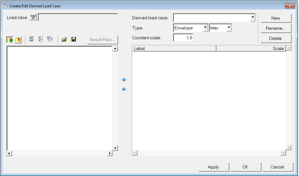
Figure 1.
This utility allows you to create envelope loadsteps using existing loadsteps and their simulation steps. Envelope loadsteps are saved to the session file. Using this utility, you can also create derived loadstepsand linear superposition loadsteps. See the Derived Load Cases topic for additional information.
Create a Derived Loadstep
-
From the Results Browser, right-click and select .
All existing loadsteps and corresponding simulations are listed.
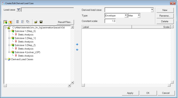 Figure 2.
 -
Click the right arrow button
 , to append the selected loadsteps to a new envelope
loadstep.
, to append the selected loadsteps to a new envelope
loadstep.
-
Leave the scale values for the selected loadsteps set to the default value of
1.0.
In this tutorial the results will not be scaled when creating the envelope loadstep.
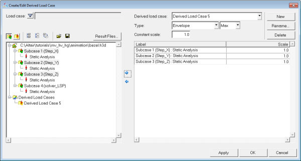 Figure 3.
 -
Click on the
 button, to view the envelope loadstep that was
created.
If there is more than one Derived Load Case displayed in the list, you can click on a derived load case to display the loadsteps which were used to create that derived load case in the table area on the right.
button, to view the envelope loadstep that was
created.
If there is more than one Derived Load Case displayed in the list, you can click on a derived load case to display the loadsteps which were used to create that derived load case in the table area on the right. -
Click on the
 button, to view the initial loadsteps in the results
file.
button, to view the initial loadsteps in the results
file.
Contouring the Envelope Loadstep
-
From the Results Browser, use the Change load case drop-down menu to set the
load case to Envelope_Max.
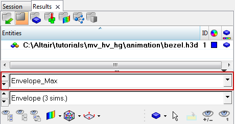 Figure 4. Note: The Results Browser can be turned on or off using the option located within the View pull-down menu.
The Change load case toolbar visibility can also be toggled on/off using the Configure Browser option (located in the Results Browser context menu).
Adding Simulation Steps from Another File
-
In the Update Result Files window, browse and select the result file
bezel_iter2.h3d.
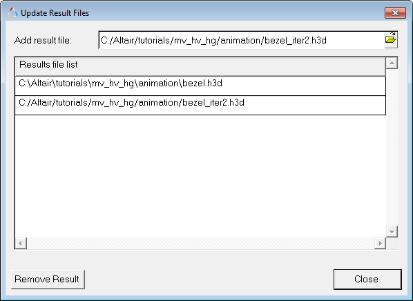 Figure 5.
 -
Click Close.
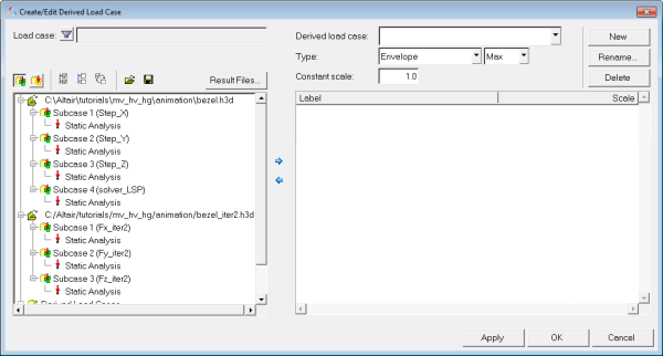 Figure 6.
 The loadsteps and simulations from the second results file will be added to the list of available loadsteps and simulations and can be used in creating derived loadsteps, linear superposition loadsteps, and envelope loadsteps.