/SENSOR
Block Format Keyword Describes the sensors which are used to activate or deactivated an object according to the defined characteristics.
Format
| (1) | (2) | (3) | (4) | (5) | (6) | (7) | (8) | (9) | (10) |
|---|---|---|---|---|---|---|---|---|---|
| /SENSOR/type/sens_ID/unit_ID | |||||||||
| sens_title | |||||||||
| Tdelay | |||||||||
Beside sensor type=TIME, additional cards are required if the following sensor types are used.
| (1) | (2) | (3) | (4) | (5) | (6) | (7) | (8) | (9) | (10) |
|---|---|---|---|---|---|---|---|---|---|
| accel_ID | Dir | Γmin | Tmin | ||||||
| (1) | (2) | (3) | (4) | (5) | (6) | (7) | (8) | (9) | (10) |
|---|---|---|---|---|---|---|---|---|---|
| gauge_ID | Pmin | Tmin | |||||||
| (1) | (2) | (3) | (4) | (5) | (6) | (7) | (8) | (9) | (10) |
|---|---|---|---|---|---|---|---|---|---|
| sens_ID1 | sens_ID2 |
| (1) | (2) | (3) | (4) | (5) | (6) | (7) | (8) | (9) | (10) |
|---|---|---|---|---|---|---|---|---|---|
| node_ID1 | node_ID2 | Wmax | Tmin | ||||||
| sect_ID | int_ID | rbody_ID | rwall_ID | ||||||
| (1) | (2) | (3) | (4) | (5) | (6) | (7) | (8) | (9) | (10) |
|---|---|---|---|---|---|---|---|---|---|
| part_ID | subset_ID | ||||||||
| IEmin | IEmax | KEmin | KEmax | Tmin | |||||
Definitions
| Field | Contents | SI Unit Example |
|---|---|---|
| type | Sensor type keyword
(see Sensor Type) |
|
| sens_ID | Sensor
identifier (Integer, maximum 10 digits) |
|
| unit_ID | Optional unit
identifier (Integer, maximum 10 digits) |
|
| sens_title | Sensor title (Character, maximum 100 characters) |
|
| Tdelay | Time
delay (Real) |
|
| Nacc | Number of accelerometers
(Nacc ≤
6) (Integer) |
|
| Ngau | Number of gauges (Ngau ≤
6) (Integer) |
|
| accel_ID | Accelerometer
identifier (Integer) |
|
| gauge_ID | Gauge
identifier (Integer) |
|
| Dir | Direction 6 (Text) |
|
| Γmin | Minimum absolute value of
acceleration (Real) |
|
| Pmin | Minimum absolute value of
pressure (Real) |
|
| Tmin | Minimum time duration
before activation when criteria is reached 6
14
15
16
17 (Real) |
|
| node_ID1 | Node identifier
1 (Integer) |
|
| node_ID2 | Node identifier
2 (Integer) |
|
| Dmin | Distance
minimum (Real) |
|
| Dmax | Distance
maximum (Real) |
|
| sens_ID1 | Activation sensor
identifier IS1 (Integer) |
|
| sens_ID2 | Deactivation sensor
identifier IS2 (Integer) |
|
| int_ID | Interface or sub-interface
identification number (Integer) |
|
| DIR | Force direction. 14
15
16
17 If type =
INTER:
If type = RWALL:
If type = RBODY:
If type = SECT:
(Integer) |
|
| rwall_ID | Rigid wall identification
number (Integer) |
|
| rbody_ID | Rigid body
identifier (Integer, maximum 10 digits) |
|
| sect_ID | Section
identifier (Integer, maximum 10 digits) |
|
| Fmin | Minimum force Default = 0 (Real, maximum 20 fields) |
|
| Fmax | Maximum force Default = 0 (Real, maximum 20 fields) |
|
| Wmax | Maximum work Default = 0 (Real, maximum 20 fields) |
|
| Fcut | Cutoff frequency. 20
(Real) |
|
| part_ID | Part identifier for the
part monitored for
/SENSOR/ENERGY. (Integer) |
|
| subset_ID | Subset identifier for the
subset monitored for /SENSOR/ENERGY. Only used if
part_ID is not defined. (Integer) |
|
| IEmin | Mininum part or subset
internal energy. Default = 0 (Real) |
|
| IEmax | Maximum part or subset
internal energy. Default = 1E+30 (Real) |
|
| KEmin | Minimum part or subset
kinetic energy. Default = 0 (Real) |
|
| KEmax | Maximum part or subset
kinetic energy. Default = 1E+30 (Real) |
Sensor Type
- Type
- Description
- TYPE0, TIME
- Start time
- TYPE1, ACCE
- Accelerometer
- TYPE2, DIST
- Nodal distance
- TYPE3, SENS
- Activation with sens_ID1
- TYPE4, AND
- ON when sensors sens_ID1 AND sens_ID1 are ON
- TYPE5, OR
- ON when sensors sens_ID1 OR sens_ID2 are ON
- TYPE6, INTER
- Activation/Deactivation of sensor by interface contact
- TYPE7, RWALL
- Activation/Deactivation of sensor by contact with rigid wall
- TYPE8, NOT
- ON when sens_ID1 is OFF
- TYPE10, GAUGE
- Pressure gauge
- TYPE11, RBODY
- Activation of sensor by Rigid Body force criteria
- TYPE12, SECT
- Activation of sensor by Section force criteria
- TYPE13, WORK
- Activation of sensor by Work criteria
- TYPE14, ENERGY
- Activation of sensor by part or subset internal or kinetic energy criteria
- USER1, USER2, USER3
- User's sensor
Comments
- The sensor types AND, OR, NOT, INTER, RWALL, RBODY and SECT work with all options using sensors.
- USER1,
USER2 and USER3 are sensors that you may
create.
The input format must be defined by a user supplied program. Refer to the Radioss User Subroutines Manual for more information about programming user sensors.
- Sensors can be used to activate airbags, imposed forces, pressures, and fixed velocities.
- Sensors can be used to activate or deactivate these elements: brick, quad, shell, truss, beam, spring or 3N Shell with /ACTIV.
- For Sensor type TIME, the sensor is activated after the time delay Tdelay. Tdelay is not applicable with the force based sensors type RWALL, INTER, RBODY, WORK or SECT.
- For Sensor type ACCE:
- Sensor is activated (at Tsensor) if one of the accelerometers
gives an acceleration greater than Γmin during a time greater
than Tmin:
Tsensor = Tdelay + Tmin
with, Tmin (time when the criteria is reached).
- Dir defines the acceleration direction:
- X
- X direction
- Y
- Y direction
- Z
- Z direction
- XY
- XY plane
- YZ
- YZ plane
- ZX
- ZX plane
- XYZ
- total acceleration
- Sensor is activated (at Tsensor) if one of the accelerometers
gives an acceleration greater than Γmin during a time greater
than Tmin:
- For Sensor type DIST:
- Nodal distance node_ID node_ID2 is defined as: Dmin < | node_ID node_ID2 | < Dmax.
-
If Dmax is reached in traction (| node_ID node_ID2 | > Dmax) or Dmin is reached in compression (| node_ID node_ID2 | < Dmin) at time Tsensor, the sensor is then activated at time Tsensor:
Tsensor = Tdelay + TR
- For Sensor type
GAUGE:
- Sensor is activated (at Tstart) if one of the gauges gives a
presure greater than Pmin during a time greater than
Tmin.
Tsensor = Tdelay + Tstart
- Tstart is the time when pressure criteria is reached.
- Sensor is activated (at Tstart) if one of the gauges gives a
presure greater than Pmin during a time greater than
Tmin.
- For Sensor types SENS,
AND, OR:
- The sensor is activated after activation of sensor sens_ID1.
- Minimum activation duration is given by Tdelay.
- After Tdelay, sensor is deactivated if sens_ID2 is activated.
- If sens_ID2=0, the sensor is deactivated after Tdelay.
- For Sensor type
SENS:
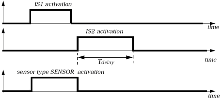
Figure 1. - For Sensor type
AND:The sensor is activated one cycle after activation at the same time as sensor sens_ID1 and sens_ID2.
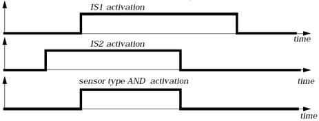
Figure 2. - For Sensor type
OR:The sensor is activated one cycle after the activation of sensor sens_ID1 or after the activation of sens_ID2.
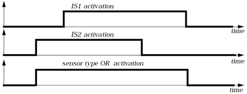
Figure 3. - For Sensor type
NOT:The sensor is activated one cycle after deactivation of sens_ID1.
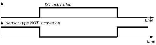
Figure 4. - For Sensor type
INTER:A Sensor is activated when contact on interface is detected, and following force criteria is satisfied:
- or during Tmin
Dir defines Force direction:- FN
- Normal Force
- TF
- Tangent Force
Sensor is deactivated if the contact is lost
If there is no impact during a time equal to Tdelay (Line 3), the sensor is deactivated.
A sensor is used for one interface or sub-interface. You can use several type INTER sensors.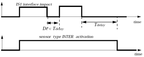
Figure 5. - For Sensor type
RWALL:
The sensor is activated one cycle after impact on the rigid wall.
A sensor is used for one rigid wall. You can use several type RWALL sensors.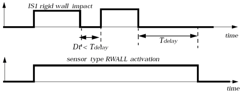
Figure 6.Sensor is activated when contact on the rigid wall is detected, and the following force criteria is satisfied:- or during Tmin
Dir defines Force direction:- FN
- Normal Force
- FT
- Tangent Force
- X
- Force in X direction
- Y
- Force in Y direction
- Z
- Force in Z direction
Sensor is deactivated if the contact is lost
- For Sensor type
RBODY:Sensor is activated when the force in the rigid body satisfies the criteria:
- or during Tmin
Dir defines Force or Moment output to monitor:- TF
- Total Force
- TM
- Total Moment
- For Sensor type
SECT:Sensor is activated when section force satisfies the criteria:
- or during Tmin
Dir defines Force direction:- TF
- Total Force
- TM
- Total Moment
- FN
- Normal Force
- FT
- Tangent Force
- FX
- Force in X direction
- FY
- Force in Y direction
- FZ
- Force in Z direction
- MX
- Moment in X direction
- MY
- Moment in Y direction
- MZ
- Moment in Z direction
- For sensor type WORK:
Sensor is activated when work satisfies the criteria:
during Tmin(1) Where,- x
- Distance between node_ID1 and node_ID2
- F(sect_ID)
- Force in the selected section force
- F(rbody_ID)
- Force in the selected rigid body
- F(int_ID)
- Force in the selected contact interface
- F(rwall_ID)
- Force in the selected rigid wall
If sect_ID is 0,
If rbody_ID is 0,
If int_ID is 0,
If rwall_ID is 0,
Work of all forces is calculated in the direction N1-N2, it is always positive.
If node_ID2 is not defined (0), the distance x becomes the displacement of the node_ID1
- For sensor type
ENERGY.The sensor is activated when the internal or kinetic energies satisfies the criteria for the defined part or subset:
- Internal energy < IEmin or Internal energy > IEmax
- Kinetic energy < KEmin or Kinetic energy > KEmax
- To obtain a class 1000 SAE filtering, the recommended value for Fcut is 1650 Hz (1.65 ms-1). Application of the filter helps to prevent wrong activation of the force-based sensor, due to a local force peak. Another method to avoid this is to use a small value for Tmin.
- Values for force and moment component limits in the force-based sensors (types RWALL, SECT) can be positive and negative. Normal, tangent, total force and moment values are always positive.