Composite Properties
Composite could be modeled with solid or shell element. Depending on the element type, the following properties can be used in Radioss to model a composite.
Shell Elements
- Layer based modeling with /PROP/TYPE10 (SH_COMP), /PROP/TYPE11 (SH_SANDW)
- Ply based modeling with /PROP/TYPE17 (STACK),
/PROP/TYPE51,
/PROP/PCOMPP+/STACK,
/PROP/TYPE19 (PLY) and /PLY
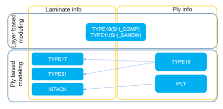
Figure 1.
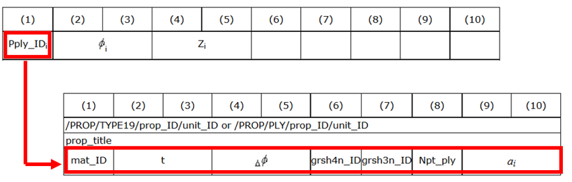
Figure 2.
Figure 3.
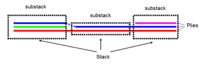
Figure 4. Stack in /PROP/TYPE51
- Layer (ply) number and integration points each layer (ply)
- Anisotropy in layer (ply)
- Layer (ply) thickness and position
- Composite material used for Layer (ply)
Layer-based Properties /PROP/TYPE10 (SH_COMP) /PROP/TYPE11 (SH_SANDW) Layer Numbers
Or Pply_IDi
Ply Numbers
=0~100 =1~100 IP of each layer/ply 1 per Layer 1 per Layer Iint Integration formulation
Anisotropic direction
√ √ + skew Anisotropic direction
√ Ply orientation change
Angle between anisotropic axis
Layer/Ply thickness
√ Ipos + Layer/Ply position
√ Ipos=2,3,4 Layer/Ply offset
mat_IDi Material for each layer/ply
Use material defined in /PART √ Must use same material type for all layers.
Commonly used Composite Material Law 15, 25 and user material 15, 25 and user material XFEM compatibility (crack propagation) √ With /FAIL/JOHNSON, /FAIL/TAB1 and /FAIL/TBUTCHER
Plyxfem Delamination between layer/ply
Minterply Material between layer/ply
Ply-based Properties /PROP/TYPE17 + /PROP/TYPE19 /PROP/TYPE51 + /PROP/TYPE19 /PROP/PCOMPP+/STACK+/PLY Layer Numbers
Or Pply_IDi
Ply Numbers
Pply_IDi=1~200 Pply_IDi=1~200 Pply_IDii1~n IP of each layer/ply 1 per Ply Npt_ply=1 in /PROP/TYPE19
1~9 per Ply Npt_ply=1~9 in /PROP/TYPE19
1~9 per Ply Npt_ply=1~9 in /PLY
Iint Integration formulation
√ Uniformed or Gauss
√ Uniformed or Gauss
Anisotropic direction
√ √ √ + skew Anisotropic direction
√ √ √ Ply orientation change
√ Defined in /PROP/TYPE19
√ Defined in /PROP/TYPE19
√ Defined in /PLY
Angle between anisotropic axis
√ in /PROP/TYPE19
√ in /PROP/TYPE19
√ in /PLY
Layer/Ply thickness
√ Different in /PROP/TYPE19
√ Different in /PROP/TYPE19
√ Different in /PLY
Ipos + Layer/Ply position
√ √ √ Ipos=2,3,4 Layer/Ply offset
√ √ √ mat_IDi Material for each layer/ply
√ Must use same material type for all plies.
√ Different material type allows for each ply.
√ Different material type allows for each ply.
Commonly used Composite Material Law 25, 27, 36, 60, 72, 93 and user material 25, ≥28 and user material 25 and user material XFEM compatibility (crack propagation) √ With /FAIL/JOHNSON and /FAIL/TBUTCHER
Plyxfem Delamination between layer/ply
√ Minterply Material between layer/ply
√ Only with LAW1+/FAIL/LAD_DAM
Layer (Ply) Number N (Nply_IDi) and Integration Points each Layer (Ply)
For layer-based modeling which use /PROP/TYPE10, /TYPE11. N is the number of layers through the shell thickness. For these properties, there is one integration point (IP) each layer.
For ply-based modeling, which use /PROP/TYPE17, /TYPE51 and /PCOMPP. Pply_IDi is the number of plies through the shell thickness. Plies could be combined until n plies for these properties.
For TYPE17 only one integration point is allowed while for TYPE51 and /STACKF until 9 integration points are allowed. Number of integration point defined with option “Npt_ply” in property TYPE19 or /PLY.
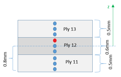
Figure 5.
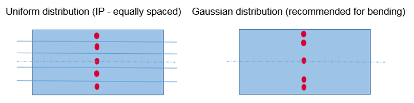
Figure 6.
It is possible to print animation results (plastic strain, damage, stress and strain tensor) in each specific integration point with /ANIM/SHELL/IDPLY/Keyword4/I/J (or /ANIM/SHELL/Keyword3/N/NIP).
For instance, use /ANIM/SHELL/IDPLY/EPSP/2/3 (or /ANIM/SHELL/EPSP/2/3) to print plastic strain in third integration point (red highlighted integration point in Figure 6) of second ply (ply name Ply12). For additional print info about Integration points through shell thickness for composite properties, refer to How is the generalized stress tensor /ANIM/SHELL/TENS/MEMB and /ANIM/SHELL/TENS/BEND computed? in the FAQs.
Anisotrophy in Layer (Ply)
- The first anisotropic direction of material could be defined with angle
and gloval vector (VX,VY,VZ).
It is also possible to use angle and skew. In this case, x-axis of skew replaced the
global vector .
Project the global vector in shell element and then rotate degree is the first anisotropic direction (also called Material direction 1). The positive direction of is coding to shell normal . For example, in Figure 7 rotate counterclockwise degree is material direction 1.
The material direction 1 of the local element reference is normally the fiber direction. Then the material character (E-Module, yield stress, and so on) of direction 1 which defined in material law could be then applied in the correct direction on local element reference.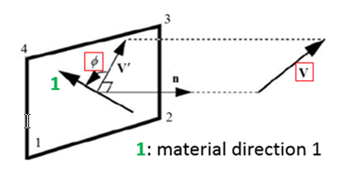
Figure 7. - Composite material could be orthotropic or anisotropic. In Radioss it is possible to describe this character with
anisotropic axis angle in ply-based properties. In case of , then it describes orthotropic material. For
layer based properties (TYPE10 and TYPE11) which without this option , so that only orthotropic material could be
defined.
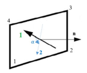
Figure 8.For property TYPE11 and TYPE51, the anisotropic direction for some shell could also be initialized with in keyword /INISHE/ORTH_LOC or /INISH3/ORTH_LOC. For property TYPE51, anisotropic axis angle could also be initialized with these keywords.
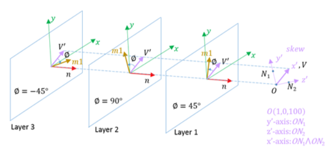
- The orientation of anisotropy for specific shell elements or shell element
groups could be change again with option drape_ID and
def_orth in /PROP/TYPE19 and /PLY.
drape_ID defined in /DRAPE. With this
feature, angle of anisotropic direction could be changed with .
- If use def_orth=1:Angle , skew or global vector will be ignored. Take shell local x-axis as vector and then rotate degree is the first anisotropic direction. (defined in /SHELL or /SH3N) is taken into account by compute angle .
(1) - If use def_orth=2 (Default)Project the global vector in shell element to vector and then rotate degree is the first anisotropic direction. The angle is computed as:
(2) 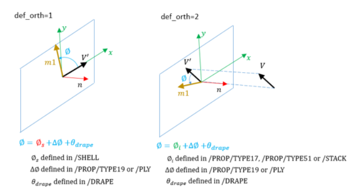
Figure 10.
- If use def_orth=1:
Layer (Ply) Thickness and Position
- For /PROP/TYPE10, layer thickness is simply averaged by layer
number
(3) and layers are automatically overlying one by one from bottom to top.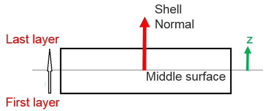
Figure 11. - For property TYPE11, TYPE17, TYPE51 and /STACK, layer (ply)
position and thickness depend on option Ipos
- If Ipos=0User layer (ply) thickness input will be taken, and layer (ply) position will be automatically overlying one by one from bottom till top; but if,
(4) Then, layer (ply) thickness will be adjusted to , so that(5) Layer (ply) position will be then adjusted, as well.
- If Ipos=1
User layer(ply) input of thickness and position will be taken. Sum of layer thickness will not be checked with .
For additional information, refer to Layer thickness and position calculation in the FAQs.
- If Ipos=0
- For property TYPE17, TYPE51 and /STACK, it is also possible
to offset the plies with Ipos=2, 3, 4
- Ipos=2: the shell element mid-surface is at
Z0 from the bottom of the ply
layout
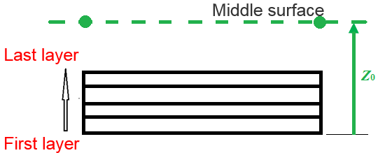
Figure 12. - Ipos=3: the top of the ply layout is coincident with the element
mid-surface
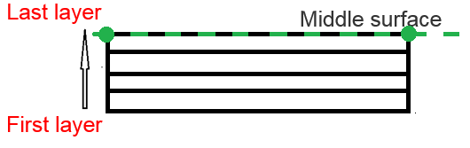
Figure 13. - Ipos=4: the bottom of the ply layout is coincident with the element
mid-surface
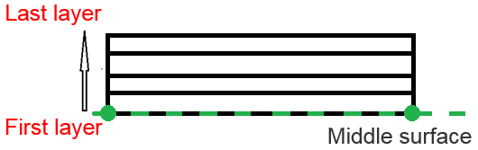
Figure 14.
- Ipos=2: the shell element mid-surface is at
Z0 from the bottom of the ply
layout
- For /PROP/TYPE17, /PROP/TYPE51 and
/STACK, ply thickness could be changed by option in /DRAPE (which is used in
/PROP/TYPE19 or /PLY). Then updated
ply thickness is:
(6)
Composite Material Used for Layer (Ply)
- Material for layer (ply)
- For property TYPE10, composite used material defined in /PART
- For property TYPE11 and TYPE17, composite used material defined in option mat_IDi. Different material ID could be defined for each layer (ply). But they must use same material type. If using LAW25, then several different LAW25 cards can be used for different layer (ply).
- For property TYPE51 and /STACK, composite also used material defined in option mat_IDi and different material type or ID could be used for each ply.
- Material between plyFor property TYPE17, it is possible to define delamination between plies or stacks (with Plyxfem=2). This is very useful for delamination is the main driven of composite failure. The material between plies defined with Minterply. For the moment, LAW1+/FAIL/LAD_DAM could be used to describe three different type of ply delamination.

Figure 15.And then in this case additional variable are added on each node of ply by computation to simulate the delamination failure between plies.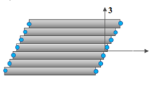
Figure 16.
Solid Element
The new composite technology allows you to make parts production more and thicker, as modeling those parts with shell elements is not enough. Thick shell can solve this problem. Compare with shell element, thick shell could direct connect with other solid part.
| Layer-based Properties | ||
|---|---|---|
| /PROP/TYPE22 (TSH_COMP) | ||
| Layer Numbers | Isolid=14: Iint=9~200 |
Isolid=15: |
| IP of each layer/ply | Inpts=ijk=2~9 | Inpts=j=1~200 |
| Integration formulation | ||
| + , Anisotropic direction | √ | |
| + skew, Anisotropic direction | √ | |
| , Ply orientation change | ||
| , Angle between anisotropic axis | ||
| , Layer/Ply thickness | √ defined with factor |
|
| Ipos + , Layer/Ply position | √ | |
| Ipos=2,3,4, Layer/Ply offset | ||
| mat_IDi, Material for each layer/ply | √ Different material type allows for each layer. |
|
| Commonly used Composite Material LAW | LAW12, LAW14, LAW25 and user material | |
| Plyxfem, Delamination between layer/ply | ||
| Minterply, Material between layer/ply | ||
- Layer Number and Integration Points Each Layer
The layer number defined using the option Iint. Iint is only used for Isolid=14 when the number of layers > 9.
In this case, the thickness direction integration point defined by Inpts should be zero.
Example, Icstr = 010; Inpts = 202; Iint = 100 for a number of 100 layers in "s" direction
- Anisotrophy in Layer (Ply)Similar to shell property /PROP/TYPE11, reference vector and angle are used to define the material direction 1. The reference vector project to the middle surface of solid element and turn degree is the material direction 1.
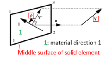
Figure 17. - Layer Thickness and Position
For solid element thickness and position defined by element mesh.
- Composite Material Used for Layer
- With option mat_IDi, it is possible to use different material type for each layer
- Composite material LAW12, LAW14 and LAW25 could be used with this property
- Failure model /FAIL/HASHIN, /FAIL/PUCK and /FAIL/LAD_DAMA with these composite material laws are also accounted for
- Material referred to in the corresponding /PART card is only used for time step and interface stiffness calculation
- For LAW25, it is assumed that (for solids and thick shells) the material is elastic in transverse direction (material direction 2 and 3) and the E33 value must be specified in such cases
For additional information, refer to “Composite material and Composite failure”.