/DRAPE
Block Format Keyword This option is used to read fiber orientation changes and thinning for a ply which are usually the result a manufacturing process simulation. Each line defines the angle change and the thinning for either a single element or a group. Each element of the ply can only be called once for a single DRAPE option.
Format
| (1) | (2) | (3) | (4) | (5) | (6) | (7) | (8) | (9) | (10) |
|---|---|---|---|---|---|---|---|---|---|
| /DRAPE/drape_ID | |||||||||
| drape_title | |||||||||
| (1) | (2) | (3) | (4) | (5) | (6) | (7) | (8) | (9) | (10) |
|---|---|---|---|---|---|---|---|---|---|
| Entity | Entity_ID | Thinning | drape | ||||||
Definitions
| Field | Contents | SI Unit Example |
|---|---|---|
| drape_ID | Drape
identifier (Integer, maximum 10 digits) |
|
| drape_title | Drape title (Character, maximum 100 characters) |
|
| Entity | Must be left justified.
(Integer) |
|
| Entity_ID | Entity
identifier (Integer) |
|
| Thinning | Ply thinning
factor (Real) |
|
| drape | Ply orientation
change (Real) |
Comments
- The drape is used in /PLY and /PROP/TYPE19 (PLY) to take into account the manufacturing process on the ply orientation and thickness of the elements. See Example (Substack with /DRAPE) in /STACK.
- For each shell element, the ply first
orthotropy direction is rotated by an angle
drape in addition to the
angles defined in the /PROP/PLY and /PLY
or in the shell definition (depending of the value of flag
def_orth in the ply input):If def_orth = 2, the angle for between the reference direction and the first direction of orthotropy is:
(1) Where, is defined in the /STACK or /PROP/TYPE17 (STACK) for ply layer i and is the angle of rotation of the layer with respect to the shell defined in the /PLY or /PROP/PLY option.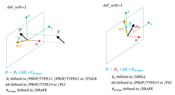
Figure 1.If def_orth = 1, the angle between the shell skew (take the shell local x-axis as vector ) and the first direction of orthotropy is:(2) Where, is defined in the shell (/SHELL or /SH3N) and is the angle of rotation of the layer with respect to the shell, defined in the /PLY or /PROP/PLY option. See Example (Substack with /DRAPE) in /STACK.
If def_orth =1, skew_ID, VX, VY, and VZ from the /PROP/TYPE17, /PROP/TYPE51 and /STACK input are ignored.
- The ply thickness ti of the element as defined in the ply is scaled using the ply thinning factor Thinning.