Iform = 6
Block Format Keyword This boundary material enables you to simulate a non-reflecting outlet boundary for multi-material law /MAT/LAW51 (Iform = 0, 1, 10, or 11). This material is useful to model an infinite domain. Elements assigned this material law act like a non-reflecting elementary boundary.
This is an improvement of the formulation used with Iform = 3 and tends to minimize wave reflections and reverse flow problems. It includes both an acoustic treatment to avoid wave reflections on the outer limits of the computational domain and a “continuity” model for the volumetric fractions.
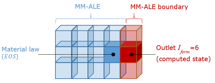
Figure 1.
Format
| (1) | (2) | (3) | (4) | (5) | (6) | (7) | (8) | (9) | (10) |
|---|---|---|---|---|---|---|---|---|---|
| /MAT/LAW51/mat_ID/unit_ID | |||||||||
| mat_title | |||||||||
| Blank Line | |||||||||
| Iform | |||||||||
| Pext | Tcp | Tca | |||||||
| (1) | (2) | (3) | (4) | (5) | (6) | (7) | (8) | (9) | (10) |
|---|---|---|---|---|---|---|---|---|---|
| Blank Line | |||||||||
| (1) | (2) | (3) | (4) | (5) | (6) | (7) | (8) | (9) | (10) |
|---|---|---|---|---|---|---|---|---|---|
| Blank Line | |||||||||
| (1) | (2) | (3) | (4) | (5) | (6) | (7) | (8) | (9) | (10) |
|---|---|---|---|---|---|---|---|---|---|
| Blank Line | |||||||||
Definitions
| Field | Contents | SI Unit Example |
|---|---|---|
| mat_ID | Material identifier. (Integer, maximum 10 digits) |
|
| unit_ID | Unit Identifier. (Interger, maximum 10 digits) |
|
| mat_title | Material title. (Character, maximum 100 characters) |
|
| Iform |
(Integer) |
|
| Pext | External pressure . Default is computed by Starter (Real) |
|
| Tcp | Characteristic time for pressure
relaxation. Default is computed by Starter (Real) |
|
| Tca | Characteristic time for volumetric
fraction relaxation . Default is computed by Starter (Real) |
|
| Initial volumetric fraction for
submaterial #j=1...3. Default is computed by Starter (Real) |
||
| Initial density for submaterial
#j=1...3. Default is computed by Starter (Real) |
||
| Initial volumetric energy for
submaterial #j=1...3. Default is computed by Starter (Real) |
||
| Pressure cut-off for submaterial
#j=1...3 . Default is computed by Starter (Real) |
||
| Initial pressure for submaterial #j=1..3
. Default is computed by Starter (Real) |
||
| Initial sound speed for submaterial
#j=1..3 . Default is computed by Starter (Real) |
Example
#---1----|----2----|----3----|----4----|----5----|----6----|----7----|----8----|----9----|---10----|
/MAT/LAW51/1
Boundary Element, AUTO-OUTLET

#    IFORM
         6
#---Global parameters------------------------------------------------------------------------------#
#               PEXT                 TCP            TC_ALPHA
                   0                   0                   0
#---Material#1:------------------------------------------------------------------------------------#
#            ALPHA_1             RHO_0_1               E_0_1             P_MIN_1               P_0_1
                   0                   0                   0                   0                   0
#              SSP_1
                   0

#---Material#2:------------------------------------------------------------------------------------#
#            ALPHA_2             RHO_0_2               E_0_2             P_MIN_2               P_0_2
                   0                   0                   0                   0                   0
#              SSP_2
                   0

#---Material#3:------------------------------------------------------------------------------------#
#            ALPHA_3             RHO_0_3               E_0_3             P_MIN_3               P_0_3
                   0                   0                   0                   0                   0
#              SSP_3
                   0

#---1----|----2----|----3----|----4----|----5----|----6----|----7----|----8----|----9----|---10----|
Comments
- This pressure formulation is
derived from Bayliss and Turkel equations. 8
(1) Where,- Acoustic impedance
- Far field pressure which is given as input unless the flux is coming inside the domain, i.e. normal velocity <0, where the stagnation pressure is imposed instead.
- Material advection is defined as:
- Outgoing flux:
The local variable is simply updated.- Incoming flux:
The local variable is no longer updated as in the previous case, because this would assume that what happened inside the domain has also happened in the far field. It is however reasonable to consider that the material is locally similar to what it was before the flow was reversed. A relaxation factor is added, allowing the incoming materials to progressively return to the imposed value given in input.
- If not defined, the global parameter Pext and the initial states are automatically computed from the adjacent elements.
- For the explosive sub-material, the initial state and data are always automatically computed using data from the adjacent elements.
- Each characteristic time can be calculated as the shortest time needed for the pressure wave (Tcp) or material (Tca) to reach the closest limit of the domain as an order of magnitude. For incompressible cases, Tcp and Tca can be taken as equal. For detonation or shock wave simulation, Tcp is calculated using an order of magnitude of the wave propagation velocity.
- It is advised that each outlet
element share one face with one element from the ALE domain(s).
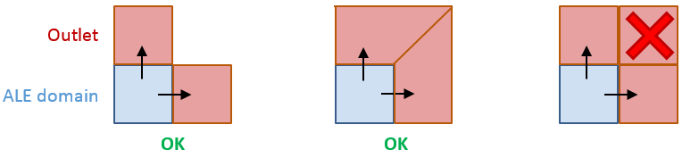
Figure 2. - The outlet boundary material is made of acoustic monopoles which imply that waves reaching the boundary should locally be approximated as plane waves or spherical waves. Therefore to correctly model the far field phenomena, the outlet elements should be located five to ten times the size of the explosive or impact area away from the explosive or impact area.
- Alvin Bayliss and Eli Turkel, Outflow boundary condition for fluid dynamics, Report 80-21, Institute for Computer Applications in Science and Engineering, NASA Langley Research Center, Hampton, Virginia