MotionSolve Models as a Functional Mockup Unit (FMU)
Learn about how you can leverage Functional Mockup Units (FMUs) to couple your MBS model with external solvers or processes to perform co-simulation or couple systems.
An FMU can be thought of as a stand-alone modeling unit that implements the Functional Mockup Interface or FMI. Converting your 3D MotionSolve model into an FMU enables you to represent your MBS system in a 1-D block environment simulator like sT/Activate.
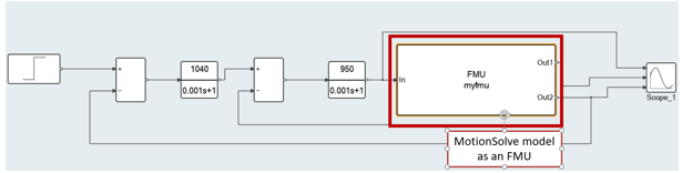
Figure 1. A MotionSolve model inside a 1D block simulation environment
A common usage scenario for FMUs is to import them into a 1-D simulator (example, Figure 1) and connect them with other systems like controls, hydraulics, thermal etc. to enable co-simulation analyses. More information on the FMI can be found here.
- Model Exchange
- Briefly, such an FMU contains within it a set of equations that must be solved by the calling program.
- Co-simulation
- Such an FMU solves its model equations independent of the calling program and only communicates certain signals to and from the calling program.
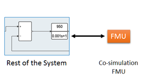
Figure 2. Coupling a co-simulation FMU with other systems in a 1-D environment
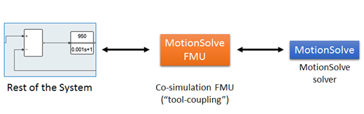
Figure 3. A MotionSolve FMU which is based on “tool-coupling” in a 1-D environment
The “tool-coupling” FMU needs to know where the MotionSolve solver is when a co-simulation is requested.
- Controls (Simulink, Activate)
- Hydraulics (Simulink, Activate, DSHPlus)
- Thermal (Simulink, Activate)
- Fluids (AcuSolve)
- Generality
- Since the FMI is a standard that is increasingly being adopted in the CAE industry, the distinct advantage of the FMI is generality. Any solver that implements the FMI can be coupled with several other solvers, systems or processes, which makes creation and management of a co-simulation pipeline easier.
- Portability
- The FMU is self-descriptive and all the libraries and resources required to run the co-simulation FMU are contained within the FMU itself. Thus, this FMU can easily be re-used between models, assemblies, systems and even machines running the same platform.
Creating an FMU from a MotionSolve Model
- The MotionView (MBS) model should contain at least a
Solver Array of type Plant Output. This solver array should refer to at least one solver
variable that act as a channel of output from the FMU. The solver variable channel ouput
from FMU becomes input to other components in the external system.
In order for the MBS model to receive input/s from the external system, a Solver Array of type Plant Input is necessary, though not mandatory to generate an FMU. This solver array also refers to one or more solver variables.
Refer to Importing and Exporting Models in the MotionView User Guide to learn to export a model as FMU.
- A description of the FMU, contained within “modelDescription.xml”.
- The MotionSolve specific FMU libraries within the “bin” folder.
- The MotionSolve model file in MDL format. If your model
contains additional property files or user subroutine files, then these are packaged
too.Note: User subroutine or property files found within the HW installation are not packaged, to manage the size of the FMU and avoid issues with software versions.
Connecting and co-simulating the MotionSolve FMU with other systems
- A HyperWorks install of version 2017.1 or later is needed.
- A HyperWorks license is required.
The license file ALTAIR_LIC.dat can be either saved into altair_install/security (the default location on Windows for altair_install for v2017 is C:/Program Files/2017) or set an environment variable ALTAIR_LICENSE_PATH that points to the license file where it is saved. This environment variable can also be used to draw license from a server. Refer to Connecting to the Altair License Manager for more details.
Set the following environment variables based on the HyperWorks version and Operating System:HyperWorks Version Windows Linux 2017/2018 ALTAIR_FMU_ROOT=altair_install NUSOL_DLL_DIR= altair_install/hwsolvers/motionsolve/bin/win64
Not available 2019 ALTAIR_FMU_ROOT=altair_install Not available 2020 ALTAIR_FMU_ROOT=altair_install ALTAIR_FMU_ROOT=altair_install LD_LIBRARY_PATH= altair_install/altair/hwsolvers/motionsolve/bin/linux64:$LD_LIBRARY_PATH
(MotionSolve solver location is being appended to the LD_LIBRARY_PATH environment variable)
RADFLEX_PATH= altair_install/altair/hwsolvers/common/bin/linux64
For the rest of this topic, we will use Activate as our 1-D simulator to demonstrate the workflow:
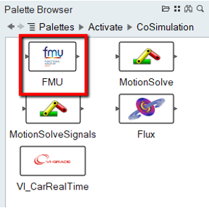
Figure 4.
- Browse to the .fmu file that was exported.
- Set the value of the input ports.
Activate by default sets a dependency vector based on the number of outputs.
- Provide an output file location for the .mrf file (MotionSolve Result File) as a string.
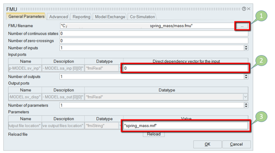
Figure 5.
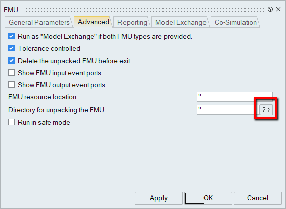
Figure 6.
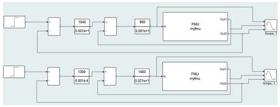
Figure 7.
MotionSolve simulation settings are controlled within the MotionSolve model, however, the simulation end time may be modified automatically depending on the simulation end time of the calling program.
Figure 8.
When a co-simulation is started, MotionSolve is invoked by the co-simulation FMU. Currently, it is assumed that a MotionSolve installation is available on the machine where the FMU is being used. Once invoked, MotionSolve talks to the calling program and communicates with it.
As with other co-simulation interfaces within MotionSolve, the quality of results is controlled by choosing an acceptable trade-off between accuracy and performance. So, simulation results obtained using a time step that is an order of magnitude smaller may be more accurate, but they will be achieved at a higher cost of performance.
A unique ability of abstracting your MBS model as an FMU is being able to connect several MotionSolve models between one another.
This allows you to connect systems that are captured in different MotionSolve models together. Since there are no restrictions on how the signals from the MotionSolve FMU are connected, you can even run multiple, stand-alone MotionSolve FMUs to compare design, for example.
See MV-7011: Co-Simulation with Activate via Function Mockup Interface (FMI) for additional information.