Spring Dampers

Use the Spring Dampers tool to edit the connectivity, properties, and initial conditions of springs and dampers.

Create Spring Dampers

A spring damper can be a coil spring damper or a torsion spring damper.

  1. From the Project Browser, select the system to which the spring damper is to be added.
  2. Right-click on a system in the Project Browser and select Add > Force Entity > SpringDamper from the context menu.
    OR
    Right-click on a spring damper folder in the Project Browser and select Add SpringDamper from the context menu.
    OR
    From the Model ribbon, click the Spring Dampers icon.
    The Add SpringDamper or SpringDamperPair dialog is displayed.
  3. Specify a label and variable name.
    By default, variables names of entities in MotionView follow a certain convention. For example, all force entities have a variable name starting with “sd_”. This is the recommended convention to follow when building models in MotionView since it has many advantages in model editing and model manipulation.
  4. Select whether to create a single spring damper or a spring damper pair.
    A spring damper entity, like most of the entities that are created in HyperWorks, can be a single entity or a pair entity. Pair entities help in creating models which have symmetric properties.
  5. Select a spring damper type from the drop-down menu.
    Option Description
    Coil Spring Generates a translational line of action force between two points on two bodies that is a function of the distance and the relative velocity between the two points.
    Torsion Spring Produces a moment between two bodies that is a function of the relative angular displacement and the relative angular velocity between the two bodies.
  6. Click OK to close the window or Apply to continue creating entities.
    Once a spring damper entity has been added to the model, the panel for the spring damper will automatically be displayed in the panel area.
Tip: For a coil spring, activate the Create explicit graphics check box to create a graphic associated with the spring damper.

Edit Spring Dampers

Define the Connectivity of Spring Dampers

The Connectivity tab on the Spring Dampers panel allows you to define the attachment bodies and endpoint points of a spring damper.

  1. If the Spring Dampers panel is not currently displayed, select the desired spring damper by clicking on it in the Project Browser or in the modeling window.
    The Spring Dampers panel is automatically displayed.
  2. Select the spring type, either coil or torsion, from the drop-down menu.
    Note: If the selected spring damper is a pair entity, first distinguish between the Left and Right tabs in the panel, and then edit the properties. When defining a pair spring damper, use pair entities for Body, Point, etc.
    Tip: Check the Symmetric properties option to make the spring properties symmetric. Once this option is activated, MotionView will ask you which side of the values of the pair entity (left or right) is to be used. Selecting any one side will make values of that side as “master” and the values of the other side will gray out and follow the values on the master side.
  3. Click the Body 1 collector and select the first body to which the spring damper is attached from the modeling window, or double-click the collector to open the Model Tree (from which the desired body can be selected).
  4. In the same manner, click the Body 2 collector and select the second body to which the spring damper is attached.
  5. Define the endpoints of the spring damper.
    For a Coil spring, use the Point 1 collector to select the point on the first body to which the spring damper is attached and the Point 2 collector for the point on the second body. After the points are defined, the distance between the two points will be displayed.

    For a Torsion spring, define a point of origin using the first Point collector and an alignment axis using the second Point collector, or, by clicking the drop-down arrow to the left of the collector, select Vector and choose a vector from the modeling window or Model Tree.

Define the Properties of Spring Dampers

The Properties tab on the Spring Dampers panel allows you to define the translational or rotational stiffness and damping properties of coil or torsion springs respectively.

  1. Click the Properties tab.
  2. For a coil spring damper, define the spring force (K) using the options in the drop down menu.
    If Linear is chosen, enter a real and positive for the linear stiffness coefficient of the coil spring.
    If Curve is chosen, define the spring force transmitted through the spring damper, expressed in the form of a curve which is a function of an independent variable.
    1. Select AKIMA, CUBIC, LINEAR , or QUINTIC under Interpolation as the method of interpolation of between two data points on the curve.
    2. Enter a value under Independent variable.
      By default, the independent variable is filled with the expression {sd.DM}, where sd is the variable name of the spring damper.
    3. Resolve the curve by double-clicking the Curve collector and selecting a curve from the Select a Curve dialog.
      Note: To use a curve, you first need to define a curve (using the Curves panel) which represents the behavior of the spring damper.
    If Sline3D is chosen, define the spring force transmitted through the spring damper, expressed in the form of a 3D spline which is a function of two independent variables.
    1. Select AKIMA, CUBIC, LINEAR , or QUINTIC under as the method of interpolation of values between 2 data points in XY plane.
    2. Resolve the 3D spline by double-clicking on the Spline3D collector and selecting a Spline3D entity from the Select a Spline3D dialog.
      Note: To use a Spline3D entity, you first need to define a spline using the Spline3D panel.
    3. Specify an expression for Independent variable X and Independent variable Z.
      By default, the Independent variable X is filled with the expression {sd.DM}, where sd is the variable name of the spring damper.
    If Expressions is chosen, enter a solver expression to define the spring force transmitted through the spring damper.
  3. Similarly, define the damping force (C) of the coil spring using the options in the drop down menu.
    If Curve is chosen, by default, the independent variable is filled with the expression {sd.VR}, where sd is the variable name of the spring damper.
    If Spline3D is chosen, by default, the Independent variable X is filled with the expression {sd.VR}, where sd is the variable name of the spring damper.
  4. For a torsion spring damper, define the spring force (KT) using the options in the drop down menu.
    If Linear is chosen, enter a real and positive for the linear rotational stiffness coefficient of the torsion spring.
    If Curve is chosen, define the spring torque transmitted through the torsion spring, expressed in the form of a curve which is a function of an independent variable.
    1. Select AKIMA, CUBIC, LINEAR , or QUINTIC under Interpolation as the method of interpolation of between two data points in the curve.
    2. Enter a value under Independent variable.
      By default, the independent variable is filled with the expression {sd.AZ}, where sd is the variable name of the spring damper.
    3. Resolve the curve by double-clicking the Curve collector and selecting a curve from the Select a Curve dialog.
      Note: To use a curve, you first need to define a curve (using the Curves panel) which represents the behavior of the spring damper.
    If Sline3D is chosen, define the spring force transmitted through the spring damper, expressed in the form of a 3D spline which is a function of two independent variables.
    1. Select AKIMA, CUBIC, LINEAR , or QUINTIC under as the method of interpolation of values between 2 data points in XY plane.
    2. Resolve the 3D spline by double-clicking on the Spline3D collector and selecting a Spline3D entity from the Select a Spline3D dialog.
      Note: To use a Spline3D entity, you first need to define a spline using the Spline3D panel.
    3. Specify an expression for Independent variable X and Independent variable Z.
      By default, the Independent variable X is filled with the expression {sd.AZ}, where sd is the variable name of the spring damper.
    If Expressions is chosen, enter a solver expression to define the damping transmitted through the spring damper.
  5. Similarly, define the damping force (CT) of the torsion spring using the options in the drop down menu.
    If Curve is chosen, by default, the independent variable is filled with the expression {sd.WZ}, where sd is the variable name of the spring damper.

    If Spline3D is chosen, by default, the Independent variable X is filled with the expression {sd.WZ}, where sd is the variable name of the spring damper.

Note:
  • For spring dampers with Linear properties, a Force_SpringDamper statement is written in MotionSolve xml.
  • Use the Curve or Expression type to define a non-linear spring or damper.
  • If a Curve or Expression type is specified for either the spring or damper property, a Force_Scalar_TwoBody statement is written to the MotionSolve xml. Any preload specified using the PreLoad tab is not considered.
  • {sd.DM} (where sd is the variable name of the spring damper) traces the distance magnitude of the two spring end points. The expression is evaluated as DM(i,j), where i is the spring damper marker on Body 1 at Point 1 and j is the spring damper marker on Body 2 at Point 2.
  • {sd.VR} traces the relative radial velocity between the two end points. The expression is evaluated as VR(i,j).
  • {sd.AZ} traces the relative rotation between the two end points. The expression is evaluated as AZ(i,j).
  • {sd.WZ} traces the relative rotational velocity between the two end points. The expression is evaluated as WZ(i,j).

Define the Preload of Spring Dampers

The Preload tab on the Spring Dampers panel allows you to specify the preload characteristics of a linear coil spring or torsion spring. Spring dampers with curve or expressions do not have separate properties since their force/torque characteristics are determined by the functions which define their stiffness properties.

  1. For a coil spring:
    1. Enter a value in the Preload field to specify the force in the linear coil spring when it is at a modeled length.
    2. Enter a value in the Free length field to specify the actual free length of the spring.
      Alternatively, click the Use Distance Between Points button to set the free length value as the distance between two end points of the spring.
  2. For a torsion spring:
    1. Enter a value in the Preload field to specify the torque produced by the linear torsion spring when it is at a specified angular displacement (Free Angle).
    2. Enter a value in the Free Angle field to specify the angular displacement produced when a torque is applied to the linear torsion spring.
Note:
  • Preload is the initial force or torque in the spring in the modeled position. The total preload can be specified by using either the Preload value, the Free Length value, or a combination of the two.
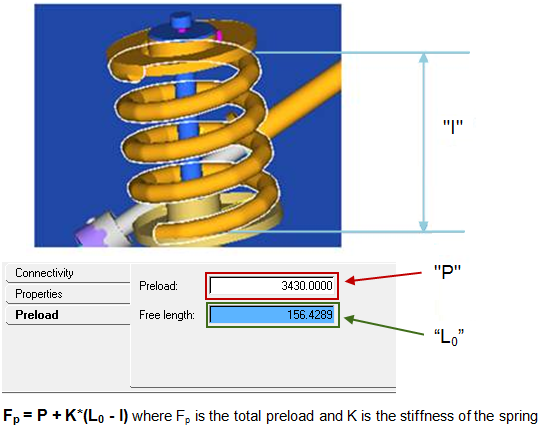

    Figure 1.
  • The total preload Fp is applied as the summation of Preload P and the force due to change in length K* (Lo –l); where K is the stiffness, Lo is the free length, and l is the modeled length of the spring (refer to the figure above).
    • For example, if the two end points of the defined spring (modeled length of spring) is 100 mm and the free-length is specified as 110, that represents the spring in a pre-deflected state by 10mm and the effective preload is 10*K; where K is the stiffness of the spring.
    • If the Preload value is specified in addition, this force is also added to the total preload.
    • In another example, if the two end points of the defined spring (modeled length of spring) is 100 mm and the free-length is 0.0, that means in the current state the spring is in an extended state by 100mm and the preload to that effect (-100*K) is applied.
  • MotionView creates a coil spring damper with a default value free-length as the distance between two end points.

Use User-Defined Properties for a Spring Damper

If desired, define the spring damper using the User-Defined tab, which will allow you to specify the properties of the spring damper using user subroutines.

  1. From the Connectivity tab, click the User-defined properties check box.
    The Properties and Preload tabs are removed.
  2. Click the newly added User-Defined tab.
  3. Define the user subroutine.
    1. Provide an expression with the USER solver function with parameters being passed to the user subroutine.
    2. Alternatively, activate the Use local file and function name check box to specify a local file where the subroutine code can be accessed by the solver.
      If this option is not specified, MotionSolve will search for a subroutine following its user subroutine loading rules.
    3. Select a function type from the drop-down menu.
    4. Select the local file for the subroutine.
      The type of file to be specified will depend on the selected function type. For example, if DLL/SO is selected, you can specify a file with a .dll extension (for Windows) or an .so extension (for Linux).
    5. Specify the function name in the subroutine that defines the entity, or accept the default name provided by HyperWorks.