A Coupler entity defines an algebraic relationship between the degrees of freedom of
two or three joints.
This constraint element may be used to model idealized spur gears, rack and pinion gears,
and differentials as simple constraints that relate the displacements in a set of joints.
Couplers can be used to specify relationships between translational, rotational, and
cylindrical joints only.
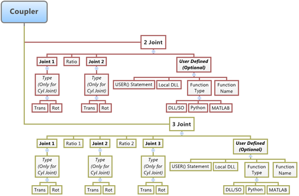
The topological information required to define an Coupler Joint is shown in the figure
below: Figure 1.
Create Couplers
From the Project Browser, select the system to which the coupler is to be
added.
Right-click on a system in the Project Browser and select Add > Constraint > Coupler from the context menu.
OR
Right-click on a coupler folder in the Project Browser and select
Add Coupler from the context menu.
OR
From the Model ribbon, click the
Couplers icon.
The Add Coupler or CouplerPair dialog is displayed.
Specify a label and variable name.
By default, variables names of entities in MotionView follow a certain convention. For example, all
coupler entities have a variable name starting with “c_”. This is the
recommended convention to follow when building models in HyperWorks since it has many advantages in model editing and model
manipulation.
Select whether to create a single coupler or a coupler pair.
A coupler entity, like most of the entities that are created in MotionView, can be a single entity or a pair entity. Pair
entities help in creating models which have symmetric properties.
Click OK to close the window or
Apply to continue creating entities.
Once a coupler entity has been added to the model, the panel for the
coupler will automatically be displayed in the panel area.
Edit Couplers
If the Couplers panel is not currently displayed, select the desired coupler by
clicking on it in the Project Browser or in the modeling window.
The Couplers panel is automatically displayed.
Select the number of joints to constrain.
Note: If the selected coupler is a pair entity, first distinguish between the
Left and Right tabs in the
panel, and then edit the properties. When defining a pair coupler, use pair
entities for the joints.
Tip: Check the Symmetric properties option to
make the coupler properties symmetric. Once this option is activated,
MotionView will ask you which side of the
values of the pair entity (left or right) is to be used. Selecting any one
side will make values of that side as “master” and the values of the other
side will gray out and follow the values on the master side.
Click on the Joint 1 collector and pick the desired
joint from the modeling window, or double-click the
collector to open the Model Tree (from which the desired
joint can be selected).
In the same manner, click the Joint 2 collector and pick
the second joint for the coupler.
If the number of joints to constrain is set to 3, repeat the same step for the
Joint 3 collector.
Note: If any of the joints are cylindrical, select the type of the displacement
to be controlled by using the drop-down menus located to the right of each
selected joint on the panel (translational or rotational).
Click the Properties tab.
In the case of a two joint coupler, type in the displacement ratio between
joint one and joint two in the appropriate box. In the case of a three joint
coupler, type in the two displacement ratios between joint one and joint two,
and between joint two and joint three.
Use User-Defined Properties for a Coupler
If desired, define the coupler using the User-Defined tab, which will allow you to
specify the properties of the coupler using user subroutines.
From the Connectivity tab, click the User-defined
properties check box.
The Properties tab is removed.
Click the newly added User-Defined tab.
Define the user subroutine.
Provide an expression with the USER solver function with parameters
being passed to the user subroutine.
Alternatively, activate the Use local file and function
name check box to specify a local file where the
subroutine code can be accessed by the solver.
If this option is not specified, MotionSolve will search for a subroutine following its user subroutine
loading rules.
Select a function type from the drop-down menu.
Select the local file for the subroutine.
The type of file to be specified will depend on the selected function
type. For example, if DLL/SO is selected, you can
specify a file with a .dll extension (for Windows)
or an .so extension (for Linux).
Specify the function name in the subroutine that defines the entity, or
accept the default name provided by HyperWorks.