Spline3D

The Spline3D panel allows you to add and edit three dimensional spline data.

Create 3D Splines

A 3D spline entity can be used to capture non-linear characteristics of a force, bushing, or motion. While a curve entity can be used to define a non-linear behavior that varies about a single independent variable, a 3D spline can be used to define non-linear behavior that varies about two independent variables. An example of such an application is the combustion force acting on the piston of a reciprocating engine. The combustion pressure, and thereby the force, is dependent on the angle of rotation of the crank and also on the speed of the crank.

  1. From the Project Browser, select the system to which the spline is to be added.
  2. Right-click on a system in the Project Browser and select Add > Reference Entity > Spline3D from the context menu.
    OR
    Right-click on a Spline3Ds folder in the Project Browser and select Add Spline3D from the context menu.
    OR
    From the Model ribbon, Splines tool set, click the Spline3Ds icon.
    The Add Spline3D dialog is displayed.
  3. Specify a label for the 3D spline.
    The spline label can be changed at any time.
  4. Specify a variable name for the 3D spline.
    By default, variables names of entities in MotionView follow a certain convention. For example, all 3D spline entities have a variable name starting with “spl3d_”. This is the recommended convention to follow when building models in MotionView since it has many advantages in model editing and model manipulation.
  5. Click OK to close the window or Apply to continue creating entities.
    Once a 3D spline entity has been added to the model, the panel for the spline will automatically be displayed in the panel area.

Edit 3D Splines

A 3D spline consists of a x-vector (or column) and more than one y-vector. Each y-vector is defined on a certain z-plane.

Define the Properties of 3D Splines

From the Properties tab, you can define the spline data.

  1. If the Spline3D panel is not currently displayed, select the desired spline by clicking on it in the Project Browser or in the modeling window.
    The Spline3D panel is automatically displayed.
  2. Select a property type from the Type drop-down menu.
  3. Define the 3D spline data.
    If File is chosen:
    1. Click on the file select icon and browse to the .csv file that contains the spline data. In this case, the model will refer to the .csv file.
      The correct format of data in the .csv file is shown below:
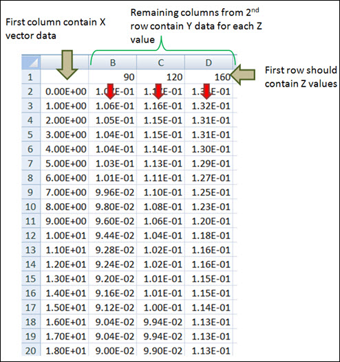
      Figure 1.
    2. View the data in a tabular format by clicking on the View Data button.
      Note: The data is displayed by factoring any offsets and scales applied in the Attributes tab (if any are applied). See the Define the Attributes of 3D Splines topic for additional information.
    3. View the spline graphically by clicking on the Show Spline button.
    If Values is chosen:
    1. Define the spline data by manually entering in values.
    2. Insert, delete, or append row data or columns (Y vectors) by right-clicking on the row or column header.
      • Selecting Insert adds a row or column before the selected row or column.
      • Selecting Delete removes the selected row or column.
      • Selecting Append adds a row or column after the last row/column.
        Note: This option will only be made available if the right-click is made on the last row/column
    3. Alternatively, if the data is available in a .csv file with the above described format, click the Import button, browse for the .csv file to be imported, and click OK.
      The data in the .csv file will be imported as values.
    Note: If the Type is set as File and a .csv file is referred, toggling to Value will not automatically import the values.
Tip: Activate Linear extrapolation if the spline data has to be linearly extrapolated at each end of the y-vector during simulation.

Define the Attributes of 3D Splines

The Attributes tab can be used to define the scale and offset for the X and Y vectors and the Z values. When a data vector is scaled, the vector is multiplied by a specified value. The original data values are not actually altered, however. Offsetting a data vector shifts the data along the corresponding axis.

You can also enter math expressions in the Scale and Offset fields.

  1. Click the Attributes tab.
  2. Enter a scaling value in the Z Scale field.
  3. Enter an offset value in the Z Offset field.
  4. Scale and offset the X and Y vectors by entering values in the appropriate fields.
    Note: The number of rows located under Y Scale and Y Offset will be equal to the number of Y vectors available in the spline data.

User-Defined Properties for a 3D Spline

If desired, define the 3D spline using the User-Defined tab, which will allow you to specify the properties of the spline using user subroutines.

  1. From the Properties tab, click the User-defined properties check box.
    The Attributes tab is hidden, as it is not applicable for this spline type.
  2. Click the newly added User-Defined tab.
  3. Define the user subroutine.
    1. Provide an expression with the USER solver function with parameters being passed to the user subroutine.
    2. Alternatively, activate the Use local file and function name check box to specify a local file where the subroutine code can be accessed by the solver.
      If this option is not specified, MotionSolve will search for a subroutine following its user subroutine loading rules.
    3. Select a function type from the drop-down menu.
    4. Select the local file for the subroutine.
      The type of file to be specified will depend on the selected function type. For example, if DLL/SO is selected, you can specify a file with a .dll extension (for Windows) or an .so extension (for Linux).
    5. Specify the function name in the subroutine that defines the entity, or accept the default name provided by HyperWorks.