Beams
Use the Beams to create beams and edit their connectivity, properties, and orientations.
Beam entity defines a straight, massless beam of uniform cross section acting between two points (Point 1 and Point 2) that belong to two different bodies (Body 1 and Body 2). The mass of the bean is lumped at Point 1 and Point 2. The stiffness properties for the beam are derived using Timoshenko beam theory.
The beam axis is assumed to be along the x-axis of the Body 2 Reference Marker. The x-axis of the Body 2 Reference Marker is also defined to be the neutral axis of the un-deformed beam. The beam is assumed to undergo small rotational deflections; large rotations are not supported.
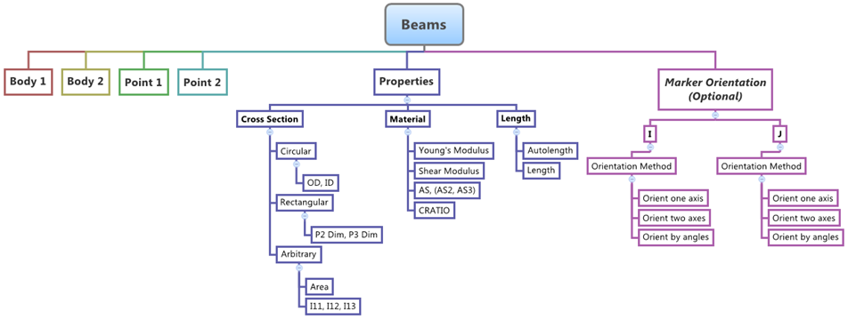
Figure 1.
Create Beams
A beam entity defines a straight, massless beam of uniform cross section acting between two points (Point 1 and Point 2) that belong to two different bodies (Body 1 and Body 2).
Edit Beams
Define the Connectivity of Beams
The Connectivity tab allows you to select the bodies and points to which a beam is attached.
Define the Properties of Beams
The Properties tab allows you to define the properties of a beam with circular, rectangular, or arbitrary cross sections.
Define the I and J Coordinate Systems of Beams
A beam has a coordinate system at each end. The I coordinate system is located at end 1 of the beam and the J coordinate system is located at end 2 of the beam. The I tab and the J tab allow you to orient each coordinate system. By default, the X axis of the J coordinate system points directly at point 1 of the beam.
Define the Preload of Beams
The Preload tab allows you to define the preload force/torque on the beam entity for MotionSolve.
This tab is not applicable for ADAMS and Abaqus.
- Click the Preload tab.
- Enter initial force preload values in the X, Y, and Z fields.
- Enter initial torque preload values in the Tx, Ty, and Tz fields.