/MAT/LAW78
Block Format Keyword This law is the Yoshida-Uemori model for describing the large-strain cyclic plasticity of metals. The law is based on the framework of two surfaces theory: the yielding surface and the bounding surface.
During the plastic deformation, a yield surface will move within the bounding surface and will never change its size, and the bounding surface can change both in size and location. The plastic-strain dependency of the Young's modulus and the work-hardening stagnation effect are also taken into account. Concerning SPH, it is compatible with solid only, this can be verified with the /SPH/WavesCompression test. The solid version is only isotropic. The shell version is anisotropic based on Hill criterion.
Format
| (1) | (2) | (3) | (4) | (5) | (6) | (7) | (8) | (9) | (10) |
|---|---|---|---|---|---|---|---|---|---|
| /MAT/LAW78/mat_ID/unit_ID | |||||||||
| mat_title | |||||||||
| E | |||||||||
| Y | b | C | h | B0 | |||||
| m | Rsat | OptR | C1 | C2 | |||||
| r00 | r45 | r90 | Mexp | Icrit | |||||
| fct_IDE | Einf | CE | |||||||
Definitions
| Field | Contents | SI Unit Example |
|---|---|---|
| mat_ID | Material identifier. (Integer, maximum 10 digits) |
|
| unit_ID | Unit Identifier. (Integer, maximum 10 digits) |
|
| mat_title | Material title. (Character, maximum 100 characters) |
|
| Initial density. (Real) |
||
| E | Young's modulus. (Real) |
|
| Poisson's ratio. (Real) |
||
| Y | Yield stress. (Real) |
|
| b | Center of the bounding
surface. (Real) |
|
| C | Parameter for kinematic hardening rule
of yield surface. (Real) |
|
| h | Material parameter for controlling work
hardening stagnation. (Real) |
|
| B0 | Initial size of the bounding
surface. (Real) |
|
| m | Parameter for isotropic and kinematic
hardening of the bounding surface. (Real) |
|
| Rsat | Saturated value of the isotropic
hardening stress. (Real) |
|
| OptR | Modified isotropic hardening rule flag
(available for shells only):
(Integer) |
|
| C1, C2 | Constant used in the modified
formulation of the isotropic hardening of bounding surface (available for shells
only). (Real) |
|
| r00 | Lankford parameter (0 degree) used for
shell elements. Default = 1.0 (Real) |
|
| r45 | Lankford parameter (45 degree) used for
shell elements. Default = 1.0 (Real) |
|
| r90 | Lankford parameter (90 degree) used for
shell elements. Default = 1.0 (Real) |
|
| Mexp | Exponent
in Barlat's 1989 Yield Criterion for shell elements.
See Comment 7.
(Real) |
|
| Icrit | Plastic criterion selection flag.
|
|
| fct_IDE | ID of the function defining the scale
factor of Young's modulus evolution versus effective plastic strain. 8 (Integer) |
|
| Einf | Asymptotic value of Young's
modulus. (Real) |
|
| CE | Parameter controlling the dependency of
Young's modulus on the effective plastic strain. (Real) |
Example
#RADIOSS STARTER
#---1----|----2----|----3----|----4----|----5----|----6----|----7----|----8----|----9----|---10----|
/UNIT/1
unit for mat
                  Mg                  mm                   s
#---1----|----2----|----3----|----4----|----5----|----6----|----7----|----8----|----9----|---10----|
#-  2. MATERIALS:
#---1----|----2----|----3----|----4----|----5----|----6----|----7----|----8----|----9----|---10----|
/MAT/LAW78/1/1
DP600-HDG
#              RHO_I
              7.8E-9
#                  E                  NU
              206000                  .3
#                  Y                   B                   C                   H                  B0
                 420                 112                 200                   0                 555
#                  m                RSAT      OPTR                  C1                  C2
                  12                 190         0                   1                   1
#                 R0                 R45                 R90                Mexp     Icrit
                   1                   1                   1
#  Fct_IDE                          EINF                  CE
         0                             1              163000
#---1----|----2----|----3----|----4----|----5----|----6----|----7----|----8----|----9----|---10----|
#ENDDATA
/END
#---1----|----2----|----3----|----4----|----5----|----6----|----7----|----8----|----9----|---10----|
Comments
- For solid elements, von Mises yield criterion is
used, so the yield function is expressed as:
(1) Whereas for shell elements, Hill’s (1948) or Barlat’s (1989) yield criterion are used, which allows for the modeling of anisotropic materials:- The Hill’s criterion is expressed as:
(2) Where,- Yield stress.
- Total back stress.
If , then is expressed as:(3) - The Barlat’s criterion is expressed as:
(4) Where, is the exponent in Barlat's yield criterion.
is expressed as:(5) With,
and .
Parameters , , and are computed from the Lankford coefficients.
, ,
Parameter is obtained by solving:(6)
- The Hill’s criterion is expressed as:
- Yield stress, Poisson ratio and Young's modulus should be strictly positive. The other parameters should be non-negative value.
- The schematic illustration of the
two-surface model is shown in Figure 1.
Where, 0 is the original center of the yield surface, the yield surface with its center and its radii Y, is moving kinematically, within a bounding surface that has a size indicated by B+R and tensor indicating its center position.
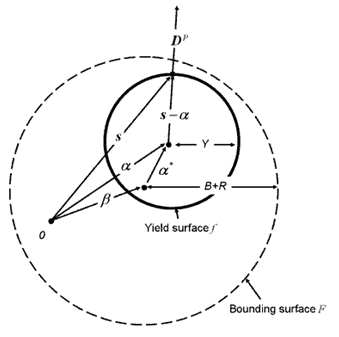
Figure 1. Schematic Drawing of the Two-surface Model - The yield surface is subjected
to a kinematic hardening. The kinematic motion is described by
that has the following evolution:
- for shell elements
- for solid elements
Where,- is the equivalent plastic strain rate
- C and a are material parameters. And
- is the total back stress
- The bounding surface is
subjected to an isotropic-kinematic hardening. The evolution equation for isotropic
hardening is:
- Default (if OptR = 0) Yoshida expression
- Available for shell elements, if OptR = 1
The evolution equation for kinematic hardening of bounding surface is:(7) - The
work-hardening stagnation during unloading is described using a
J2-type surface
with a radius r and a center
q:
(8) Where, should be either inside or on the surface .
- The exponent in Barlat’s (1989) yield
criterion can be set by considering the microstructure of the material. Any value greater
than 2.0 is valid, but typically:
- Mexp = 6.0 (Default) for a Body Centered Cubic (BCC) material
- Mexp = 8.0 for a Face Centered Cubic (FCC) material
- The evolution of Young's modulus:
- If fct_IDE > 0, the curve defines a scale factor for Young's modulus
evolution with equivalent plastic strain, which means the Young's modulus is scaled by
the function
:
The initial value of the scale factor should be equal to 1 and it decreases.
-
If fct_IDE = 0, the Young's modulus is calculated as:
(9) Where,
E and Einf are respectively the initial and asymptotic value of Young's modulus, is the accumulated equivalent plastic strain.
Note: If fct_IDE = 0 and CE = 0, Young's modulus E is kept constant.
- If fct_IDE > 0, the curve defines a scale factor for Young's modulus
evolution with equivalent plastic strain, which means the Young's modulus is scaled by
the function
:
- This material law is not available for implicit analysis.