/MONVOL/FVMBAG2

Block Format Keyword Describes Finite Volume Method Airbag, which has simplified input, similar to /MONVOL/FVMBAG1.

  • Gas materials are specified in separate /MAT/GAS cards.
  • Composition of injected gas mixture and injector properties are specified in separate /PROP/INJECT1 or /PROP/INJECT2 cards.

Format

(1) (2) (3) (4) (5) (6) (7) (8) (9) (10)
/MONVOL/FVMBAG2/monvol_ID/unit_ID
monvol_title
surf_IDex surf_IDin Hconv            
mat_ID       Pext T0   Ittf
Number of injectors
(1) (2) (3) (4) (5) (6) (7) (8) (9) (10)
Njet                  
Repeat the next line Njet times to define each injector
(1) (2) (3) (4) (5) (6) (7) (8) (9) (10)
inject_ID sens_ID surf_IDinj              
Number of vent holes and porous fabric surfaces
(1) (2) (3) (4) (5) (6) (7) (8) (9) (10)
Nvent Nporsurf                
Define Nvent vent holes (four lines per vent hole and optional line for Chemkin vent)
(1) (2) (3) (4) (5) (6) (7) (8) (9) (10)
surf_IDv Iform Avent Bvent     vent_title
Tstart Tstop Δ P d e f Δ t P d e f   IdtPdef
fct_IDt fct_IDP fct_IDA   Fscalet FscaleP FscaleA
fct_IDt' fct_IDP' fct_IDA'   Fscalet' FscaleP' FscaleA'
Chemkin model data (read only Iform =2
(1) (2) (3) (4) (5) (6) (7) (8) (9) (10)
fct_IDv   Fscalev  
Define Nporsurf porous surfaces (two lines per vent hole and optional line for Chemkin porosity)
(1) (2) (3) (4) (5) (6) (7) (8) (9) (10)
surf_IDps Iformps Iblockage           surface_title
Tstart Tstop Δ P d e f Δ t P d e f    
Chemkin model data (read only if Iformps = 2)
(1) (2) (3) (4) (5) (6) (7) (8) (9) (10)
fct_ID_psV   Fscale_psV            
Numerical and meshing parameters
(1) (2) (3) (4) (5) (6) (7) (8) (9) (10)
Cgmerg Tswitch   Iswitch Pswitch    
Δ T sca Δ T min      

Definitions

Field Contents SI Unit Example
monvol_ID Monitored volume identifier.

(Integer, maximum 10 digits)

 
unit_ID Unit Identifier.

(Integer, maximum 10 digits)

 
monvol_title Monitored volume title.

(Character, maximum 100 characters)

 
surf_IDex External surface identifier. 1 2

(Integer)

 
surf_IDin Internal surface identifier.

(Integer)

 
Hconv Heat transfer coefficient. 17

(Real)

[ W m 2 K ]
mat_ID Initial gas material identifier.

(Integer)

 
Pext External pressure.

(Real)

[ Pa ]
T0 Initial temperature.

Default = 295K (Real)

[ K ]
Ittf Time shift flag.
Active only when at least one injection sensor is specified. Determines time shift for venting and porosity options when injection starts at a Time to Fire specified in a sensor.
= 0 (Default)
=1 and 2
Obsolete.
=3
All options are shifted. 7

(Integer)

 
Njet Number of injectors.

(Integer)

 
inject_ID Injector property identifier.

(Integer)

 
sens_ID Sensor identifier.

(Integer)

 
surf_IDinj Injector surface identifier (must be different for each injector).

(Integer)

 
Nvent Number of vent holes.

(Integer)

 
Nporsurf Number of porous surfaces.

(Integer)

 
surf_IDv Vent holes area surface identifier.

(Integer)

 
Iform Venting formulation. 5
= 0
Set to 1
= 1 (Default)
Isenthalpic
= 2
Chemkin
= 3
Local
= 4
Isenthalpic with possible gas (mat_ID) flow-in.

(Integer)

 
Avent If surf_IDv ≠ 0: scale factor on vent hole area.

Default = 1.0 (Real)

 
If surf_IDv = 0: vent hole area.

Default = 0.0 (Real)

[ m 2 ]
Bvent If surf_IDv ≠ 0: scale factor on impacted vent hole area.

Default = 1.0 (Real)

 
If surf_IDv = 0: Bvent is reset to 0 for vent hole area.

Default = 0.0 (Real)

[ m 2 ]
vent_title Vent hole title.

(Character, maximum 20 characters)

 
Tstart Start time for venting.

Default = 0 (Real)

[ s ]
Tstop Stop time for venting.

Default = 1030 (Real)

[ s ]
Δ P d e f Pressure difference to open vent hole membrane.

Δ P d e f = P d e f P e x t

Default = 0 (Real)

[ Pa ]
Δ t P d e f Minimum duration pressure exceeds Pdef to open vent hole membrane.

Default = 0 (Real)

[ s ]
IdtPdef Time delay flag when Δ P d e f is reached:
= 0
Pressure should be over Δ P d e f during a Δ t P d e f cumulative time to activate venting.
= 1
Venting is activated Δ t P d e f after Δ P d e f is reached.

(Integer)

 
fct_IDt Vent area scale factor vs time function identifier.

(Integer)

 
fct_IDP Vent area scale factor vs pressure function identifier.

(Integer)

 
fct_IDA Vent area scale factor vs area function identifier.

(Integer)

 
Fscalet Scale factor for fct_IDt.

Default = 1.0 (Real)

 
FscaleP Scale factor for fct_IDP.

Default = 1.0 (Real)

 
FscaleA Scale factor for fct_IDA.

Default = 1.0 (Real)

 
fct_IDt' Vent area scale factor vs time during contact function identifier.

(Integer)

 
fct_IDP' Vent area scale factor vs pressure during contact function identifier.

(Integer)

 
fct_IDA' Vent area scale factor vs impacted surface function identifier.

(Integer)

 
Fscalet' Scale factor for fct_IDt'.

Default = 1.0 (Real)

 
FscaleP' Scale factor for fct_IDP'.

Default = 1.0 (Real)

 
FscaleA' Scale factor for fct_IDA'.

Default = 1.0 (Real)

 
fct_IDv Outflow velocity function identifier (Chemkin model, only if Iform = 2).

(Integer)

 
Fscalev Scale factor on fct_IDv.

Default = 1.0 (Real)

[ m s ] MathType@MTEF@5@5@+= feaagKart1ev2aaatCvAUfeBSjuyZL2yd9gzLbvyNv2CaerbuLwBLn hiov2DGi1BTfMBaeXatLxBI9gBaerbd9wDYLwzYbItLDharqqtubsr 4rNCHbGeaGqiVu0Je9sqqrpepC0xbbL8F4rqqrFfpeea0xe9Lq=Jc9 vqaqpepm0xbba9pwe9Q8fs0=yqaqpepae9pg0FirpepeKkFr0xfr=x fr=xb9adbaqaaeGaciGaaiaabeqaamaabaabaaGcbaWaamWaaeaada Wcaaqaaiaab2gaaeaacaqGZbaaaaGaay5waiaaw2faaaaa@39DE@
surf_IDps Porous surface identifier.

(Integer)

 
Iformps Porosity formulation.
= 1 (Default)
Bernouilli (Wang & Nefske).
= 2
Chemkin.
= 3
Graefe.

(Integer)

 
Iblockage Block porous leakage flag, when in contact (Iformps > 0).
= 0
No
= 1
Yes

(Integer)

 
surface_title Porous surface title.

(Character, maximum 20 characters)

 
fct_ID_psV Outflow velocity versus relative pressure function identifier.

(Integer)

 
Fscale_psV Scale factor on fct_ID_psV.

Default = 1.0 (Real)

[ m s ] MathType@MTEF@5@5@+= feaagKart1ev2aaatCvAUfeBSjuyZL2yd9gzLbvyNv2CaerbuLwBLn hiov2DGi1BTfMBaeXatLxBI9gBaerbd9wDYLwzYbItLDharqqtubsr 4rNCHbGeaGqiVu0Je9sqqrpepC0xbbL8F4rqqrFfpeea0xe9Lq=Jc9 vqaqpepm0xbba9pwe9Q8fs0=yqaqpepae9pg0FirpepeKkFr0xfr=x fr=xb9adbaqaaeGaciGaaiaabeqaamaabaabaaGcbaWaamWaaeaada Wcaaqaaiaab2gaaeaacaqGZbaaaaGaay5waiaaw2faaaaa@39DE@
Cgmerg Factor for global merging. 16

Default = 0.02 (Real)

 
Tswitch Amount of time after airbag time to fire to switch from FVM to UP (Uniform Pressure) formulation. 20

Default = 1e30 (Real)

[ s ]
Iswitch Flag to switch from FVM to UP.
= 0 (Default)
No switch to uniform pressure. The finite volume method is used.
= 1
Switch is performed when either Pswitch or Tswitch criteria is reached.

(Integer)

 
Pswitch Ratio of FV standard deviation pressure to average pressure which triggers FVM to UP switch. 21

Default = 0.0 (Real)

 
Δ T sca Scale factor for airbag time step.

Using /DT/FVMBAG in the Engine will override this value.

Default = 0.9

 
Δ T min Minimum time step for the airbag.

Using /DT/FVMBAG in the Engine will override this value.


Comments

  1. The airbag external surface should be built only from 4- and 3-noded shell elements. The airbag external surface cannot be defined with option /SURF/SEG, nor with /SURF/SURF, if a sub-surface is defined in /SURF/SEG.
  2. External surfaces shall compose a closed volume with normals must oriented outwards.
  3. The correct model units must defined in /BEGIN or a local /UNIT referenced by unit_ID. The gas constants, injection velocity, and predefined gas materials are set based on the units defined in the model.
  4. Pressure and temperature of external air and the initial pressure and temperature of air inside of airbag is set to Pext and T0.
  5. Venting through vent holes:

    If Iform = 1, venting velocity is computed from Bernoulli equation using local pressure in the airbag.

    The exit velocity is given by:(1)
    u 2 = 2 γ γ 1 P ρ ( 1 ( P ext P ) γ 1 γ )

    The mass out flow rate is given by:

    If Iform = 2, venting velocity is computed from the Chemkin equation:(2)
    v = F s c a l e v f v ( P P e x t ) MathType@MTEF@5@5@+= feaagKart1ev2aqatCvAUfeBSjuyZL2yd9gzLbvyNv2CaerbuLwBLn hiov2DGi1BTfMBaeXatLxBI9gBaerbd9wDYLwzYbItLDharqqtubsr 4rNCHbGeaGqiVu0Je9sqqrpepC0xbbL8F4rqqrFfpeea0xe9Lq=Jc9 vqaqpepm0xbba9pwe9Q8fs0=yqaqpepae9pg0FirpepeKkFr0xfr=x fr=xb9adbaqaaeGaciGaaiaabeqaamaabaabaaGcbaGaamODaiabg2 da9iaadAeacaWGZbGaam4yaiaadggacaWGSbGaamyzamaaBaaaleaa caWG2baabeaakiabgwSixlaadAgadaWgaaWcbaGaamODaaqabaGcca GGOaGaamiuaiabgkHiTiaadcfadaWgaaWcbaGaamyzaiaadIhacaWG 0baabeaakiaacMcaaaa@4A01@

    Where, f v MathType@MTEF@5@5@+= feaagKart1ev2aqatCvAUfeBSjuyZL2yd9gzLbvyNv2CaerbuLwBLn hiov2DGi1BTfMBaeXatLxBI9gBaerbd9wDYLwzYbItLDharqqtubsr 4rNCHbGeaGqiVu0Je9sqqrpepC0xbbL8F4rqqrFfpeea0xe9Lq=Jc9 vqaqpepm0xbba9pwe9Q8fs0=yqaqpepae9pg0FirpepeKkFr0xfr=x fr=xb9adbaqaaeGaciGaaiaabeqaamaabaabaaGcbaGaamOzamaaBa aaleaacaWG2baabeaaaaa@3809@ is defined by fct_IDv.

    If Iform = 3, venting velocity is equal to the component of the local fluid velocity normal to vent hole surface. Local density and energy are used to compute outgoing mass and energy through the hole.

  6. When there is no sensor which activates gas injection, the vent holes and porosity becomes active, if time T becomes greater than the Tstart, or if the pressure P exceeds Pdef value longer than the time given in Δ t P d e f .
  7. When at least one of the injectors is activated by the sensor, then activation of venting and porosity options is controlled by Ittf.

    Tinj is the time of the first injector to be activated by the sensor.

    Ittf = 0
      Venting, Porosity
    Activation When P > Δ P d e f longer than the time Δ t P d e f , or T > T s t a r t
    Deactivation Tstop
    Time dependent functions No shift
    Ittf = 3
      Venting, Porosity
    Activation When T > T i n j and P > Δ P d e f longer than the time Δ t P d e f , or T > T i n j + T s t a r t
    Deactivation T i n j + T s t o p
    Time dependent functions Shifted by T i n j + T s t a r t

    All other related curves are active when the corresponding venting, porosity or communication option is active.

    The variety of Ittf values comes from historical reasons. Values Ittf=1 and 2 are obsolete and should not be used. Usual values are Ittf=0 (no shift) or Ittf=3 (all relative options are shifted by Tinj).

  8. If surf_IDv0 (surf_IDv is defined) the vent hole area is computed as:(3)
    v e n t _ h o l e s _ a r e a   = A v e n t f A ( A A 0 ) f t ( t ) f P ( P P e x t ) MathType@MTEF@5@5@+= feaagKart1ev2aqatCvAUfeBSjuyZL2yd9gzLbvyNv2CaerbuLwBLn hiov2DGi1BTfMBaeXatLxBI9gBaerbd9wDYLwzYbItLDharqqtubsr 4rNCHbGeaGqiVu0Je9sqqrpepC0xbbL8F4rqqrFfpeea0xe9Lq=Jc9 vqaqpepm0xbbG8FasPYRqj0=yi0dXdbba9pGe9xq=JbbG8A8frFve9 Fve9Ff0dmeaabaqaciGacaGaaeqabaWaaeaaeaaakeaaqaaaaaaaaa WdbiaadAhacaWGLbGaamOBaiaadshacaGGFbGaamiAaiaad+gacaWG SbGaamyzaiaadohacaGGFbGaamyyaiaadkhacaWGLbGaamyyaiaabc cacqGH9aqppaGaamyqamaaBaaaleaacaWG2bGaamyzaiaad6gacaWG 0baabeaakiabgwSixlGacAgadaWgaaWcbaGaamyqaaqabaGcdaqada qaamaalaaabaGaamyqaaqaaiaadgeadaWgaaWcbaGaaGimaaqabaaa aaGccaGLOaGaayzkaaGaeyyXICTaciOzamaaBaaaleaacaWG0baabe aakmaabmaabaGaamiDaaGaayjkaiaawMcaaiabgwSixlGacAgadaWg aaWcbaGaamiuaaqabaGcdaqadaqaaiaadcfacqGHsislcaWGqbWaaS baaSqaaiaadwgacaWG4bGaamiDaaqabaaakiaawIcacaGLPaaaaaa@65A1@
    Where,
    A MathType@MTEF@5@5@+= feaagKart1ev2aqatCvAUfeBSjuyZL2yd9gzLbvyNv2CaerbuLwBLn hiov2DGi1BTfMBaeXatLxBI9gBaerbd9wDYLwzYbItLDharqqtubsr 4rNCHbGeaGqiVu0Je9sqqrpepC0xbbL8F4rqqrFfpeea0xe9Lq=Jc9 vqaqpepm0xbbG8FasPYRqj0=yi0dXdbba9pGe9xq=JbbG8A8frFve9 Fve9Ff0dmeaabaqaciGacaGaaeqabaWaaeaaeaaakeaacaWGbbaaaa@3725@
    Area of surface surf_IDv
    A 0 MathType@MTEF@5@5@+= feaagKart1ev2aqatCvAUfeBSjuyZL2yd9gzLbvyNv2CaerbuLwBLn hiov2DGi1BTfMBaeXatLxBI9gBaerbd9wDYLwzYbItLDharqqtubsr 4rNCHbGeaGqiVu0Je9sqqrpepC0xbbL8F4rqqrFfpeea0xe9Lq=Jc9 vqaqpepm0xbbG8FasPYRqj0=yi0dXdbba9pGe9xq=JbbG8A8frFve9 Fve9Ff0dmeaabaqaciGacaGaaeqabaWaaeaaeaaakeaacaWGbbWaaS baaSqaaiaaicdaaeqaaaaa@380B@
    Initial area of surface surf_IDv
    f t , f P and f A
    Functions of fct_IDt, fct_IDP and fct_IDA
  9. In the case of activated venting closure the vent holes surface is computed as:(4)
    v e n t _ h o l e s _ a r e a   = A v e n t A n o n _ i m p a c t e d f t ( t ) f P ( P P e x t ) f A ( A n o n _ i m p a c t e d A 0 ) MathType@MTEF@5@5@+= feaagKart1ev2aqatCvAUfeBSjuyZL2yd9gzLbvyNv2CaerbuLwBLn hiov2DGi1BTfMBaeXatLxBI9gBaerbd9wDYLwzYbItLDharqqtubsr 4rNCHbGeaGqiVu0Je9sqqrpepC0xbbL8F4rqqrFfpeea0xe9Lq=Jc9 vqaqpepm0xbbG8FasPYRqj0=yi0dXdbba9pGe9xq=JbbG8A8frFve9 Fve9Ff0dmeaabaqaciGacaGaaeqabaWaaeaaeaaakeaaqaaaaaaaaa WdbiaadAhacaWGLbGaamOBaiaadshacaGGFbGaamiAaiaad+gacaWG SbGaamyzaiaadohacaGGFbGaamyyaiaadkhacaWGLbGaamyyaiaabc cacqGH9aqppaGaamyqamaaBaaaleaacaWG2bGaamyzaiaad6gacaWG 0baabeaakiabgwSixlaadgeadaWgaaWcbaGaamOBaiaad+gacaWGUb Gaai4xaiaadMgacaWGTbGaamiCaiaadggacaWGJbGaamiDaiaadwga caWGKbaabeaakiabgwSixlGacAgadaWgaaWcbaGaamiDaaqabaGcda qadaqaaiaadshaaiaawIcacaGLPaaacqGHflY1ciGGMbWaaSbaaSqa aiaadcfaaeqaaOWaaeWaaeaacaWGqbGaeyOeI0IaamiuamaaBaaale aacaWGLbGaamiEaiaadshaaeqaaaGccaGLOaGaayzkaaGaeyyXICTa ciOzamaaBaaaleaacaWGbbaabeaakmaabmaabaWaaSaaaeaacaWGbb WaaSbaaSqaaiaad6gacaWGVbGaamOBaiaac+facaWGPbGaamyBaiaa dchacaWGHbGaam4yaiaadshacaWGLbGaamizaaqabaaakeaacaWGbb WaaSbaaSqaaiaaicdaaeqaaaaaaOGaayjkaiaawMcaaaaa@7F75@
    (5)
    + B vent A impacted f t ( t ) f P ( P P ext ) f A ( A impacted A 0 )
    With impacted surface:(6)
    A impacted = e S vent n c ( e ) n ( e ) A e
    and non-impacted surface:(7)
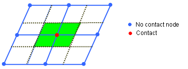
    A non _ impacted = e S vent ( 1 n c ( e ) n ( e ) ) A e

    Image12
    Figure 1.
    Where for each element e of the vent holes surf_IDv, n c ( e ) means the number of impacted nodes among the n ( e ) nodes defining the element.

    A0 is the initial area of surface surf_IDv

    ft, fP and fA are functions of fct_IDt, fct_IDP and fct_IDA

    ft', fP' and fA' are functions of fct_IDt', fct_IDP' and fct_IDA'

  10. Radioss ends with a Starter error, if surf_IDv = 0 (surf_IDv is not defined) for Chemkin venting formulation (Iform=2).
  11. Functions fct_IDt and fct_IDP are equal to 1, if they are not specified (null identifier).
  12. Function fct_IDA is assumed to be equal to 1, if it is not specified.
  13. To account for contact blockage of vent holes and porous surface areas, flag IBAG must be set to 1 in the correspondent interfaces (Line 3 of interface /INTER/TYPE7 or /INTER/TYPE23). If not, the nodes impacted into the interface are not considered as impacted nodes in the previous formula for Aimpacted and Anon_impacted.
  14. Leakage by porosity formulations, the mass flow rate flowing out is computed as:
    • Iformps = 1 m ˙ out = A eff 2 P ρ Q 1 γ γ γ 1 [ 1 Q γ 1 γ ] (Isentropic - Wang Nefske)
    • Iformps = 2 m ˙ out = A eff ρ v ( P P ext )

      Where, v is the outflow gas velocity (Chemkin)

    • Iformps = 3 m ˙ out = A eff 2 ρ ( P P ext ) (Graefe)

    The effective venting area Aeff is computed according to the input in the /LEAK/MAT input for fabric materials of TYPE19 or TYPE58.

  15. If leakage blockage is activated, Iblockage=1, the effective venting area is modified as:(8)
    A eff = A non _ impacted

    A non _ impacted is non-impact surface

    The blockage will be active only if flag IBAG is set to 1 in the concerned contact interfaces (line 3 of interface TYPE7, TYPE19 and TYPE23).

  16. When a finite volume fails during the inflation process of the airbag (volume becoming negative, internal mass or energy becoming negative), it is merged to one of its neighbors so that the calculation can continue. Two merging approaches are used:
    • Global merging: a finite volume is merged if its volume becomes less than a certain factor multiplying the mean volume of all the finite volumes. The flag Igmerg determines if the mean volume to use is the current mean volume (Igmerg =1) or the initial mean (Igmerg =2). The factor giving the minimum volume from the mean volume is Cgmerg.
    • Time step dependent merging: if the time step for a finite volume becomes less than the value defined in /DT/FVMBAG, the finite volume is merged with neighboring finite volumes.
  17. The lost heat flow is given by:(9)
    Q ˙ ( x , t ) = H conv Area ( x , t ) ( T ( x , t ) T 0 )
  18. If an element of a vent hole surface (surf_IDv) belongs to an injector (surf_IDinj) it will be ignored from the vent hole. A constant correction factor f computed at time t=0 is applied to the total vent hole surface:(10)
    f = S vent S vent S injector
  19. If an element of a porous surface also belongs to an injector (surf_IDinj), it will be ignored from the porous surface.
  20. The time to switch Tswitch to Uniform Pressure is relative to the time to fire. The switch is automatic, if there is only one finite volume left.
  21. Pswitch is the ratio of standard deviation of the Finite Volume pressures to the airbag average pressure.(11)
    P s w i t c h = SD(FV pressure) Average pressure MathType@MTEF@5@5@+= feaagKart1ev2aqatCvAUfeBSjuyZL2yd9gzLbvyNv2CaerbuLwBLn hiov2DGi1BTfMBaeXatLxBI9gBaerbd9wDYLwzYbItLDharqqtubsr 4rNCHbGeaGqiVu0Je9sqqrpepC0xbbL8F4rqqrFfpeea0xe9Lq=Jc9 vqaqpepm0xbba9pwe9Q8fs0=yqaqpepae9pg0FirpepeKkFr0xfr=x fr=xb9adbaqaaeGaciGaaiaabeqaamaabaabaaGcbaGaamiuamaaBa aaleaacaWGZbGaam4DaiaadMgacaWG0bGaam4yaiaadIgaaeqaaOGa eyypa0ZaaSaaaeaacaqGtbGaaeiraiaabIcacaqGgbGaaeOvaiaabc cacaqGWbGaaeOCaiaabwgacaqGZbGaae4CaiaabwhacaqGYbGaaeyz aiaabMcaaeaacaqGbbGaaeODaiaabwgacaqGYbGaaeyyaiaabEgaca qGLbGaaeiiaiaabchacaqGYbGaaeyzaiaabohacaqGZbGaaeyDaiaa bkhacaqGLbaaaaaa@5916@

    This ratio can be output using the /TH/MONVOL variable UPCRIT. Pswitch approaches zero as the pressure in each finite volume approaches the average pressure in the airbag.