/MONVOL/AIRBAG1
Block Format Keyword Describes one-chambered airbag with hybrid input of injected gas. This keyword is similar to /MONVOL/AIRBAG (Obsolete), but has more flexible input.
- Gas materials specified in separate /MAT/GAS cards
- Composition of injected gas mixture and injector properties specified in separate /PROP/INJECT1 or /PROP/INJECT2 cards
Format
| (1) | (2) | (3) | (4) | (5) | (6) | (7) | (8) | (9) | (10) |
|---|---|---|---|---|---|---|---|---|---|
| /MONVOL/AIRBAG1/monvol_ID/unit_ID | |||||||||
| monvol_title | |||||||||
| surf_IDex | Hconv | ||||||||
| Ascalet | AscaleP | AscaleS | AscaleA | AscaleD | |||||
| mat_ID | Pext | T0 | Iequil | Ittf | |||||
| (1) | (2) | (3) | (4) | (5) | (6) | (7) | (8) | (9) | (10) |
|---|---|---|---|---|---|---|---|---|---|
| Njet |
| (1) | (2) | (3) | (4) | (5) | (6) | (7) | (8) | (9) | (10) |
|---|---|---|---|---|---|---|---|---|---|
| inject_ID | sens_ID | Ijet | node_ID1 | node_ID2 | node_ID3 |
| (1) | (2) | (3) | (4) | (5) | (6) | (7) | (8) | (9) | (10) |
|---|---|---|---|---|---|---|---|---|---|
| fct_IDPt | FscalePt | ||||||||
| (1) | (2) | (3) | (4) | (5) | (6) | (7) | (8) | (9) | (10) |
|---|---|---|---|---|---|---|---|---|---|
| Nvent | Nporsurf |
| (1) | (2) | (3) | (4) | (5) | (6) | (7) | (8) | (9) | (10) |
|---|---|---|---|---|---|---|---|---|---|
| surf_IDv | Iform | Avent | Bvent | vent_title | |||||
| Tstart | Tstop | IdtPdef | |||||||
| fct_IDt | fct_IDP | fct_IDA | Fscalet | FscaleP | FscaleA | ||||
| fct_IDt' | fct_IDP' | fct_IDA' | Fscalet' | FscaleP' | FscaleA' | ||||
| (1) | (2) | (3) | (4) | (5) | (6) | (7) | (8) | (9) | (10) |
|---|---|---|---|---|---|---|---|---|---|
| fct_IDv | Fscalev | ||||||||
| (1) | (2) | (3) | (4) | (5) | (6) | (7) | (8) | (9) | (10) |
|---|---|---|---|---|---|---|---|---|---|
| surf_IDps | Iformps | Iblockage | surface_title | ||||||
| Tstart | Tstop | IdtPdef | |||||||
| (1) | (2) | (3) | (4) | (5) | (6) | (7) | (8) | (9) | (10) |
|---|---|---|---|---|---|---|---|---|---|
| Cps | Areaps | fct_IDcps | fct_IDaps | Fscalecps | Fscaleaps | ||||
| (1) | (2) | (3) | (4) | (5) | (6) | (7) | (8) | (9) | (10) |
|---|---|---|---|---|---|---|---|---|---|
| fct_ID_psv | Fscale_psv | ||||||||
Definitions
| Field | Contents | SI Unit Example |
|---|---|---|
| monvol_ID | Monitored volume
identifier. (Integer, maximum 10 digits) |
|
| unit_ID | Unit Identifier. (Integer, maximum 10 digits) |
|
| monvol_title | Monitored volume
title. (Character, maximum 100 characters) |
|
| surf_IDex | External surface
identifier. (Integer) |
|
| Hconv | Heat transfer coefficient.
17 (Real) |
|
| Ascalet | Abscissa scale factor for
time-based functions. Default = 1.0 (Real) |
|
| AscaleP | Abscissa scale factor for
pressure-based functions. Default = 1.0 (Real) |
|
| AscaleS | Abscissa scale factor for
area-based functions. Default = 1.0 (Real) |
|
| AscaleA | Abscissa scale factor for
angle-based functions. Default = 1.0 (Real) |
|
| AscaleD | Abscissa scale factor for
distance-based functions. Default = 1.0 (Real) |
|
| mat_ID | Material identifier for
initial gas (/MAT/GAS). (Real) |
|
| Volumetric
viscosity. Default = 0.01 (Real) |
||
| Pext | External
pressure. (Real) |
|
| T0 | Initial
temperature. Default = 295K (Real) |
|
| Iequil | Initial thermodynamic
equilibrium flag.
(Integer) |
|
| Ittf | Time shift flag. Active
only when at least one injection sensor is specified. Determines
time shift for venting and porosity options when injection
starts at a Time to Fire specified in a sensor.
(Integer) |
|
| Njet | Number of
injectors. (Integer) |
|
| inject_ID | Injector property
identifier. (Integer) |
|
| sens_ID | Sensor
identifier. (Integer) |
|
| Ijet | Jetting flag.
(Integer) |
|
| node_ID1, node_ID2, node_ID3 | Node identifiers N1, N2, and N3 for jet shape definition. (Integer) |
|
| fct_IDPt | If
Ijet = 1:
identifier of the function number defining
. (Integer) |
|
| If
Ijet = 1:
identifier of the function number defining
. (Integer) |
||
| If
Ijet = 1:
identifier of the function number defining
. (Integer) |
||
| FscalePt | If
Ijet = 1:
scale factor for
fct_IDPt. Default = 1.0 (Real) |
|
| If
Ijet = 1:
scale factor for
. Default = 1.0 (Real) |
||
| If
Ijet = 1:
scale factor for
. Default = 1.0 (Real) |
||
| Nvent | Number of vent
holes. (Integer) |
|
| Nporsurf | Number of porous
surfaces. (Integer) |
|
| surf_IDv | Vent holes area surface
identifier. (Integer) |
|
| Iform | Formulation flag.
(Integer) |
|
| Avent | If surf_IDv ≠ 0: scale factor on vent
hole area. Default = 1.0 (Real) |
|
| If surf_IDv = 0: vent hole
area. Default = 0.0 (Real) |
||
| Bvent | If surf_IDv ≠ 0: scale factor on
impacted vent hole area. Default = 1.0 (Real) |
|
| If surf_IDv = 0:
Bvent is
reset to 0 for vent hole area. Default = 0.0 (Real) |
||
| vent_title | Vent hole
title. (Character, maximum 20 characters) |
|
| Tstop | Stop time for
venting. Default = 1030 (Real) |
|
| Tstart | Start time for
venting. Default = 0 (Real) |
|
| Pressure difference to
open vent hole membrane.
Default = 0 (Real) |
||
| Minimum duration pressure
exceeds Pdef to
open vent hole membrane. Default = 0 (Real) |
||
| IdtPdef | Time delay flag when
is reached:
(Integer) |
|
| fct_IDt | Porosity vs time function
identifier. (Integer) |
|
| fct_IDp | Porosity vs pressure
function identifier. (Integer) |
|
| fct_IDA | Porosity vs area function
identifier. (Integer) |
|
| Fscalet | Scale factor for
fct_IDt. Default = 1.0 (Real) |
|
| FscaleP | Scale factor for fct_IDp. Default = 1.0 (Real) |
|
| FscaleA | Scale factor for
fct_IDA. Default = 1.0 (Real) |
|
| If
Ijet = 1:
identifier of the function number defining
. (Integer) |
||
| FscalePt | If
Ijet = 1:
scale factor for
fct_IDPt. Default = 1.0 (Real) |
|
| If
Ijet = 1:
scale factor for
. Default = 1.0 (Real) |
||
| If
Ijet = 1:
scale factor for
. Default = 1.0 (Real) |
||
| Nvent | Number of vent
holes. (Integer) |
|
| fct_IDt' | Porosity vs time when
contact function identifier. (Integer) |
|
| fct_IDP' | Porosity vs pressure when
contact function identifier. (Integer) |
|
| fct_IDA' | Porosity vs impacted
surface function identifier. (Integer) |
|
| Fscalet' | Scale factor for
fct_IDt'. Default = 1.0 (Real) |
|
| FscaleP' | Scale factor for
fct_IDP'. Default = 1.0 (Real) |
|
| FscaleA' | Scale factor for
fct_IDA'. Default = 1.0 (Real) |
|
| fct_IDv | Outflow velocity function
identifier (Chemkin model, only if Iform = 2). (Integer) |
|
| Fscalev | Scale factor on
fct_IDv. Default = 1.0 (Real) |
|
| surf_IDps | Porous surface identifier
(ignored if Iformps
=0). (Integer) |
|
| Iformps | Porosity formulation.
(Integer) |
|
| Iblockage | Block leakage flag, if
contact (Iformps > 0).
(Integer) |
|
| surface_title | Porous surface
title. (Character, maximum 20 characters) |
|
| Cps | Scale factor on leakage
area (Iformps
=0). (Real) |
|
| Areaps | Leakage area
(Iformps
=0). (Real) |
|
| fct_IDcps | Function identifier
defining
Cps(t),
ignored if Cps is
not equal to zero. (Integer) |
|
| fct_IDaps | Function identifier
defining
Areaps(P-Pext),
ignored if Areaps
is not equal to zero. (Integer) |
|
| Fscalecps | Scale factor for
fct_IDcps. Default = 1.0 (Real) |
|
| Fscaleaps | Scale factor for
fct_IDaps. Default = 1.0 (Real) |
|
| fct_ID_psv | Outflow velocity function
identifier (Chemkin model, only if
Iformps =
2). (Integer) |
|
| Fscale_psv | Scale factor on
fct_ID_psv. Default = 1.0 (Real) |
Comments
- The airbag external surface should be built only from 4- and 3-noded shell elements. The airbag external surface cannot be defined with /SURF/SEG, or with /SURF/SURF, if a sub-surface is defined in /SURF/SEG.
- The volume must be closed and the normals must be oriented outwards.
- Abscissa scale factors are used
to transform abscissa units in airbag functions, for example:
(1) Where,- Time
- Function of fct_IDt
(2) Where,- Pressure
- Function of fct_IDP
- Pressure and temperature of external air and the initial pressure and temperature of air inside of airbag is set to Pext. and T0.
- Initial thermodynamic
equilibrium is written at time zero (Iequil =0) or at beginning of
jetting (Iequil =1), based on the following
equation with respect to the volume at time zero, or the volume at beginning of
jetting:
(3) Where,- Mass of gas initially filling the airbag
- Molar mass of the gas initially filling the airbag
- Gas constant depending on the units system given in
/BEGIN card. For example in SI
system:
(4)
- If jetting is used, an additional
pressure is applied to each element of the
airbag:
(5) With m being the normalized vector between the projection of the center of the element upon segment (N1 and N3) and the center of the element; the angle between vectors MN2 and m (in degrees), the distance between the center of the element and its projection upon segment (N1 and N3).
The projection of a point upon segment (N1 and N3) is defined as the projection of the point in direction MN2 upon the line (N1 and N3) if it lies inside the segment (N1 and N3). If this is not the case, the projection of the point upon segment (N1 and N3) is defined as the closest node N1 or N3.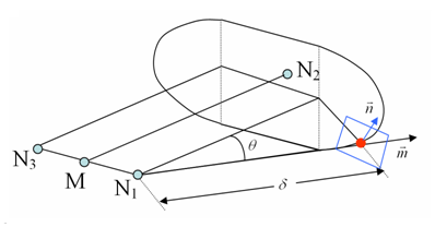
Figure 1. Dihedral Shape of the Jetwith M between of N1 and N3
- If node_ID3 = 0, node_ID is set to node_ID1 and the dihedral shape is reduced to a conical shape.
- If
fct_IDv = 0:
isenthalpic outflow is assumed, else Chemkin model is used and outflow velocity
is:
(6) Where, is the function of fct_IDv.- Isenthalpic model
Venting or the expulsion of gas from the volume is assumed to be isenthalpic.
The flow is also assumed to be unshocked, coming from a large reservoir and through a small orifice with effective surface area, A.
Conservation of enthalpy leads to velocity, u, at the vent hole. The Bernouilli equation is then written as:
(monitored volume) (vent hole)
Applying the adiabatic conditions:
(monitored volume) (vent hole)
Where, is the pressure of gas into the airbag and is the density of gas into the airbag.
Therefore, the exit velocity is given by:(7) For supersonic flows the outlet velocity is determined as described in Supersonic Outlet Flow in the Theory Manual.
The mass out flow rate is given by:(8) The energy flow rate is given by:(9) Where, is the airbag volume and is the internal energy of gas into the airbag.
- Chemkin model
(10) Where, is the density of the gas within the airbag and is the function of fct_IDv.
- Isenthalpic model
- Vent hole area is computed
as:
(11) With impacted surface:(12) and non-impacted surface:(13) 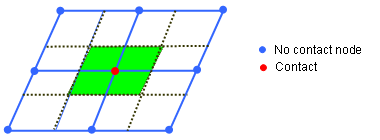
Figure 2.Where for each element e of the airbag materials means the number of impacted nodes among the nodes defining the element and is the area of element e.
And,
A0 is the initial area of surface surf_IDv
, and are functions of fct_IDt, fct_IDP and fct_IDA
, and are functions of fct_IDt', fct_IDP' and fct_IDA'
- Functions fct_IDt' and fct_IDP' are assumed to be equal to 1, if they are not specified (null identifier).
- If function
fct_IDA' is not specified,
it is assumed as:
(14) - To account for contact blockage of vent holes and porous surface area, flag IBAG must be set to 1 in the correspondent interfaces (Line 3 of interface TYPE7 or TYPE23). If not, the nodes impacted into the interface are not considered as impacted nodes in the previous formula for Aimpacted and Anon_impacted.
- When there is no sensor which activates gas injection, the vent hole membrane is deflated, if time T becomes greater than the Tstart or if the pressure P exceeds Pdef value longer than the time given in .
- When at least one of the
injectors is activated by the sensor, then the activation of venting and
porosity options is controlled by
Ittf
Tinj is the time of the first injector to be activated by the sensor.
Ittf = 0:
Venting, Porosity Activation When longer than the time , or Deactivation Tstop Time dependent functions No shift Ittf = 3:Venting, Porosity Activation When and longer than the time , or Deactivation Time dependent functions Shifted by All other related curves are active when the corresponding venting, porosity or communication option is active.
The variety of Ittf values comes from historical reasons. Values Ittf =1 and 2 are obsolete and should not be used. Usual values are Ittf =0 (no shift) or Ittf =3 (all relative options are shifted by Tinj).
- Leakage by porosity formulations; the mass
flow rate flowing out is computed as:
- Iformps = 0
(Isentropic - Wang Nefske)
with
and or
is the function of fct_IDcps and is function of fct_IDaps
The effective venting area Aeff does not vary with different airbag fabric materials.
If Iformps > 0, the effective venting area Aeff is computed according to the input in the /LEAK/MAT input for fabric materials of TYPE19 or TYPE58.
Iformps = 1 (Isentropic - Wang Nefske)
Iformps = 2Where, is the outflow gas velocity (Chemkin).
Iformps = 3 (Graefe)
- Iformps = 0
(Isentropic - Wang Nefske)
- If leakage blockage is activated,
Iblockage=1, the effective venting area is modified
as:
(15) Anon_impacted is non-impacted surface 11.
The blockage will be active only if flag IBAG is set to 1 in the concerned contact interfaces (line 3 of interface TYPE7 and TYPE23).
- The lost heat flow is given
by:
(16)