/INTER/LAGDT/TYPE7

Block Format Keyword Describes the interface TYPE7 with constant minimum time step. Which means same behavior as interface TYPE7 with possible switch to Lagrange multiplier formulation, if minimum time step defined with /DT/INTER/CST is reached.

Description

The main limitations are:
  • Same limitation as interface TYPE7 with Lagrange Multiplier formulation.
  • Friction is not working after switching into Lagrange Multiplier formulation.
  • Not yet compatible with SPMD.

Format

(1) (2) (3) (4) (5) (6) (7) (8) (9) (10)
/INTER/LAGDT/TYPE7/inter_ID/unit_ID
inter_title
grnd_IDs surf_IDm Istf   Igap   Ibag Idel    
Fscalegap Gapmax            
Stmin Stmax            
Stfac Fric Gapmin Tstart Tstop
IBC     Inacti VISs VISF Bumult
Ifric Ifiltr Xfreq Iform          
Read this input only if Ifric > 0
(1) (2) (3) (4) (5) (6) (7) (8) (9) (10)
C1 C2 C3 C4 C5
Read this input only if Ifric > 1
(1) (2) (3) (4) (5) (6) (7) (8) (9) (10)
C6                

Definitions

Field Contents SI Unit Example
inter_ID Interface identifier

(Integer, maximum 10 digits)

 
unit_ID Unit Identifier

(Integer, maximum 10 digits)

 
inter_title Interface title

(Character, maximum 100 characters)

 
grnd_IDs Secondary nodes group identifier

(Integer)

 
surf_IDm Main surface identifier

(Integer)

 
Istf Stiffness definition flag. 4
= 0
Stfac is a stiffness scale factor and the stiffness is computed according to the main side characteristics.
= 1
Stfac is a stiffness value.
= 2, 3, 4 and 5
Stfac and the stiffness is computed from both main and secondary characteristics.

(Integer)

 
Igap Gap/element option flag.
= 0
Gap is constant and equal to the minimum gap.
= 1
Gap varies accordingly to the characteristics of the impacted main surface and the impacting secondary node.
= 2
Variable gap + gap scale correction of the computed gap.

(Integer)

 
Ibag Airbag vent holes closure flag in case of contact.
= 0 (Default)
No closure
= 1
Closure

(Integer)

 
Idel Node and segment deletion flag. 2
= 0 (Default)
No deletion
= 1
When all the elements (4-node shells, 3-node shells, solids) associated to one segment are deleted, the segment is removed from the main side of the interface. It is also removed in case of explicit deletion using Radioss Engine keyword /DEL in the Engine file.
Additionally, non-connected nodes are removed from the secondary side of the interface.
= 2
When a 4-node shell, a 3-node shell or a solid element is deleted, the corresponding segment is removed from the main side of the interface. It is also removed in case of explicit deletion using Radioss Engine keyword /DEL in the Engine file.
Additionally, non-connected nodes are removed from the secondary side of the interface.
= -1
Same as = 1, except non-connected nodes are not removed from the secondary side of the interface.
= -2
Same as = 2, except non-connected nodes are not removed from the secondary side of the interface.

(Integer)

 
Fscalegap Gap scale factor.

Default = 1.0 (Real)

 
Gapmax Maximum gap.
= 0
No maximum value for the gap.

(Real)

[ m ]
Stmin Minimum stiffness.

(Real)

[ N m ]
Stmax Maximum stiffness.

Default = 1030 (Real)

[ N m ]
Stfac Interface stiffness, if Istf = 1

Default = 0 (Real)

[ N m ]
Stiffness scale factor for the interface, if Istf = 0

Default = 1.0 (Real)

Fric Coulomb friction

(Real)

 
Gapmin Minimum gap for impact activation

(Real)

[ m ]
Tstart Start time

(Real)

[ t ]
Tstop Time for temporary deactivation

(Real)

[ t ]
IBC Deactivation flag of boundary conditions at impact

(Boolean)

 
Inacti Deactivation flag of stiffness in case of initial penetrations. 8
= 0
No action.
= 1
Deactivation of stiffness on nodes.
= 2
Deactivation of stiffness on elements.
= 3
Change node coordinates to avoid initial penetrations.
= 5
Gap is variable with time and initial gap is computed as follows:
gap 0 = Gap P 0
with P 0 MathType@MTEF@5@5@+= feaagKart1ev2aaatCvAUfeBSjuyZL2yd9gzLbvyNv2CaerbuLwBLn hiov2DGi1BTfMBaeXatLxBI9gBaerbd9wDYLwzYbItLDharqqtubsr 4rNCHbGeaGqiVu0Je9sqqrpepC0xbbL8F4rqqrFfpeea0xe9Lq=Jc9 vqaqpepm0xbba9pwe9Q8fs0=yqaqpepae9pg0FirpepeKkFr0xfr=x fr=xb9adbaqaaeGaciGaaiaabeqaamaabaabaaGcbaGaamiuamaaBa aaleaacaaIWaaabeaaaaa@37B1@ being the initial penetration.
= 6
Gap is variable with time but initial penetration is computed as follows (the node is slightly depenetrated):
gap 0 = Gap P 0 5 % ( Gap P 0 )

(Integer)

 
VISs Critical damping coefficient on interface stiffness.

Default set to 0.05 (Real)

 
VISF Critical damping coefficient on interface friction. 16

Default set to 1.0 (Real)

 
Bumult Sorting factor. 11 12

Default set to 0.20 (Real)

 
Ifric Friction formulation flag. 15
= 0 (Default)
Static Coulomb friction law
= 1
Generalized viscous friction law
= 2
(Modified) Darmstad friction law
= 3
Renard friction law

(Integer)

 
Ifiltr Friction filtering flag. 16
= 0 (Default)
No filter is used
= 1
Simple numerical filter
= 2
Standard -3dB filter with filtering period
= 3
Standard -3dB filter with cutting frequency

(Integer)

 
Xfreq Filtering coefficient.

Should have a value between 0 and 1.

(Real)

 
Iform Friction penalty formulation type.
= 1 (Default)
Viscous (total) formulation.
= 2
Stiffness (incremental) formulation.

(Integer)

 
C1 Friction law coefficient

(Real)

 
C2 Friction law coefficient

(Real)

 
C3 Friction law coefficient

(Real)

 
C4 Friction law coefficient

(Real)

 
C5 Friction law coefficient

(Real)

 
C6 Friction law coefficient

(Real)


Flags for Deactivation of Boundary Conditions: IBC

(1)-1 (1)-2 (1)-3 (1)-4 (1)-5 (1)-6 (1)-7 (1)-8
          IBCX IBCY IBCZ

Definitions

Field Contents SI Unit Example
IBCX Deactivation flag of X boundary condition at impact
= 0
Free DOF
= 1
Fixed DOF

(Boolean)

 
IBCY Deactivation flag of Y boundary condition at impact
= 0
Free DOF
= 1
Fixed DOF

(Boolean)

 
IBCZ Deactivation flag of Z boundary condition at impact
= 0
Free DOF
= 1
Fixed DOF

(Boolean)


Comments

  1. For the flag Ibag, refer to the monitored volume option (Monitored Volumes (Airbags)).
  2. Flag Idel = 1 has a CPU cost higher than Idel = 2.
  3. If Igap = 2, the variable gap is computed as:(1)
    max { Gap min , min [ Fscale gap ( g s + g m ) , Gap max ] }

    The values given in Line 4 are ignored if Igap2.

  4. Contact stiffness computed as:
    • For Istf = 0, stiffness

      K= K m MathType@MTEF@5@5@+= feaagKart1ev2aaatCvAUfeBSjuyZL2yd9gzLbvyNv2CaerbuLwBLn hiov2DGi1BTfMBaeXatLxBI9gBaerbd9wDYLwzYbItLDharqqtubsr 4rNCHbGeaGqiVu0Je9sqqrpepC0xbbL8F4rqqrFfpeea0xe9Lq=Jc9 vqaqpepm0xbbG8FasPYRqj0=yi0dXdbba9pGe9xq=JbbG8A8frFve9 Fve9Ff0dmeaabaqaciGacaGaaeqabaWaaeaaeaaakeaacaWGlbGaey ypa0Jaam4samaaBaaaleaacaWGTbaabeaaaaa@3A22@

    • For Istf > 1, stiffness(2)
      K = max [ S t min , min ( S t max , K n ) ]
      Where,
      • K n MathType@MTEF@5@5@+= feaagKart1ev2aaatCvAUfeBSjuyZL2yd9gzLbvyNv2CaerbuLwBLn hiov2DGi1BTfMBaeXatLxBI9gBaerbd9wDYLwzYbItLDharqqtubsr 4rNCHbGeaGqiVu0Je9sqqrpepC0xbbL8F4rqqrFfpeea0xe9Lq=Jc9 vqaqpepm0xbbG8FasPYRqj0=yi0dXdbba9pGe9xq=JbbG8A8frFve9 Fve9Ff0dmeaabaqaciGacaGaaeqabaWaaeaaeaaakeaacaWGlbWaaS baaSqaaiaad6gaaeqaaaaa@384D@ is computed from both main segment stiffness K m MathType@MTEF@5@5@+= feaagKart1ev2aaatCvAUfeBSjuyZL2yd9gzLbvyNv2CaerbuLwBLn hiov2DGi1BTfMBaeXatLxBI9gBaerbd9wDYLwzYbItLDharqqtubsr 4rNCHbGeaGqiVu0Je9sqqrpepC0xbbL8F4rqqrFfpeea0xe9Lq=Jc9 vqaqpepm0xbbG8FasPYRqj0=yi0dXdbba9pGe9xq=JbbG8A8frFve9 Fve9Ff0dmeaabaqaciGacaGaaeqabaWaaeaaeaaakeaacaWGlbWaaS baaSqaaiaad6gaaeqaaaaa@384D@ and secondary node stiffness K s MathType@MTEF@5@5@+= feaagKart1ev2aaatCvAUfeBSjuyZL2yd9gzLbvyNv2CaerbuLwBLn hiov2DGi1BTfMBaeXatLxBI9gBaerbd9wDYLwzYbItLDharqqtubsr 4rNCHbGeaGqiVu0Je9sqqrpepC0xbbL8F4rqqrFfpeea0xe9Lq=Jc9 vqaqpepm0xbbG8FasPYRqj0=yi0dXdbba9pGe9xq=JbbG8A8frFve9 Fve9Ff0dmeaabaqaciGacaGaaeqabaWaaeaaeaaakeaacaWGlbWaaS baaSqaaiaad6gaaeqaaaaa@384D@

        Istf = 2, K n = K m + K s 2

        Istf = 3, K n = max ( K m , K s )

        Istf = 4, K n = min ( K m , K s )

        Istf = 5, K n = K m K s K m + K s

      • K m MathType@MTEF@5@5@+= feaagKart1ev2aaatCvAUfeBSjuyZL2yd9gzLbvyNv2CaerbwvMCKf MBHbqefqvATv2CG4uz3bIuV1wyUbqedmvETj2BSbqefm0B1jxALjhi ov2DaebbnrfifHhDYfgasaacH8srps0lbbf9q8WrFfeuY=Hhbbf9v8 qqaqFr0xc9pk0xbba9q8WqFfea0=yr0RYxir=Jbba9q8aq0=yq=He9 q8qqQ8frFve9Fve9Ff0dmeaacaGacmGadaWaaiqacaabaiaafaaake aacaWGlbWaaSbaaSqaaiaad2gaaeqaaaaa@3AC5@ is main segment stiffness and computed as:

        When main segment lies on a shell or is shared by shell and solid(3)
        K m = Stfac 0.5 E t
        When main segment lies on a solid:(4)
        K m = B S 2 V
        Where,
        S MathType@MTEF@5@5@+= feaagKart1ev2aaatCvAUfeBSjuyZL2yd9gzLbvyNv2CaerbwvMCKf MBHbqefqvATv2CG4uz3bIuV1wyUbqedmvETj2BSbqefm0B1jxALjhi ov2DaebbnrfifHhDYfgasaacH8srps0lbbf9q8WrFfeuY=Hhbbf9v8 qqaqFr0xc9pk0xbba9q8WqFfea0=yr0RYxir=Jbba9q8aq0=yq=He9 q8qqQ8frFve9Fve9Ff0dmeaacaGacmGadaWaaiqacaabaiaafaaake aacaWGtbaaaa@39AF@
        Segment area
        V MathType@MTEF@5@5@+= feaagKart1ev2aaatCvAUfeBSjuyZL2yd9gzLbvyNv2CaerbwvMCKf MBHbqefqvATv2CG4uz3bIuV1wyUbqedmvETj2BSbqefm0B1jxALjhi ov2DaebbnrfifHhDYfgasaacH8srps0lbbf9q8WrFfeuY=Hhbbf9v8 qqaqFr0xc9pk0xbba9q8WqFfea0=yr0RYxir=Jbba9q8aq0=yq=He9 q8qqQ8frFve9Fve9Ff0dmeaacaGacmGadaWaaiqacaabaiaafaaake aacaWGtbaaaa@39AF@
        Volume of the solid
        B MathType@MTEF@5@5@+= feaagKart1ev2aaatCvAUfeBSjuyZL2yd9gzLbvyNv2CaerbwvMCKf MBHbqefqvATv2CG4uz3bIuV1wyUbqedmvETj2BSbqefm0B1jxALjhi ov2DaebbnrfifHhDYfgasaacH8srps0lbbf9q8WrFfeuY=Hhbbf9v8 qqaqFr0xc9pk0xbba9q8WqFfea0=yr0RYxir=Jbba9q8aq0=yq=He9 q8qqQ8frFve9Fve9Ff0dmeaacaGacmGadaWaaiqacaabaiaafaaake aacaWGtbaaaa@39AF@
        Bulk modulus
        K s MathType@MTEF@5@5@+= feaagKart1ev2aaatCvAUfeBSjuyZL2yd9gzLbvyNv2CaerbwvMCKf MBHbqefqvATv2CG4uz3bIuV1wyUbqedmvETj2BSbqefm0B1jxALjhi ov2DaebbnrfifHhDYfgasaacH8srps0lbbf9q8WrFfeuY=Hhbbf9v8 qqaqFr0xc9pk0xbba9q8WqFfea0=yr0RYxir=Jbba9q8aq0=yq=He9 q8qqQ8frFve9Fve9Ff0dmeaacaGacmGadaWaaiqacaabaiaafaaake aacaWGlbWaaSbaaSqaaiaad2gaaeqaaaaa@3AC5@
        An equivalent nodal stiffness considered for interface TYPE7, and computed as:
        • When node is connected to a shell element:(5)
          K s = Stfac 1 2 E t
        • When node is connected to a solid element:(6)
          K s = Stfac B V 3

    There is no limitation to the value of stiffness factor (but a value larger than 1.0 can reduce the initial time step).

  5. The values given in Line 5 are ignored if Istf < 1.
  6. A default value for Gapmin is computed as the minimum of:(7)
    G a p min = min ( t , l 10 , l min 2 )
    Where,
    t MathType@MTEF@5@5@+= feaagKart1ev2aaatCvAUfeBSjuyZL2yd9gzLbvyNv2CaerbwvMCKf MBHbqefqvATv2CG4uz3bIuV1wyUbqedmvETj2BSbqefm0B1jxALjhi ov2DaebbnrfifHhDYfgasaacH8srps0lbbf9q8WrFfeuY=Hhbbf9v8 qqaqFr0xc9pk0xbba9q8WqFfea0=yr0RYxir=Jbba9q8aq0=yq=He9 q8qqQ8frFve9Fve9Ff0dmeaacaGacmGadaWaaiqacaabaiaafaaake aacaWGtbaaaa@39AF@
    Average thickness of the main shell elements
    l MathType@MTEF@5@5@+= feaagKart1ev2aaatCvAUfeBSjuyZL2yd9gzLbvyNv2CaerbwvMCKf MBHbqefqvATv2CG4uz3bIuV1wyUbqedmvETj2BSbqefm0B1jxALjhi ov2DaebbnrfifHhDYfgasaacH8srps0lbbf9q8WrFfeuY=Hhbbf9v8 qqaqFr0xc9pk0xbba9q8WqFfea0=yr0RYxir=Jbba9q8aq0=yq=He9 q8qqQ8frFve9Fve9Ff0dmeaacaGacmGadaWaaiqacaabaiaafaaake aacaWGtbaaaa@39AF@
    Average side length of the main brick elements
    l min MathType@MTEF@5@5@+= feaagKart1ev2aaatCvAUfeBSjuyZL2yd9gzLbvyNv2CaerbwvMCKf MBHbqefqvATv2CG4uz3bIuV1wyUbqedmvETj2BSbqefm0B1jxALjhi ov2DaebbnrfifHhDYfgasaacH8srps0lbbf9q8WrFfeuY=Hhbbf9v8 qqaqFr0xc9pk0xbba9q8WqFfea0=yr0RYxir=Jbba9q8aq0=yq=He9 q8qqQ8frFve9Fve9Ff0dmeaacaGacmGadaWaaiqacaabaiaafaaake aacaWGlbWaaSbaaSqaaiaad2gaaeqaaaaa@3AC5@
    The smallest side length of all main segments (shell or brick)
  7. The gap is computed for each impact as:(8)
    Fscale g a p ( g s + g m )
    Where,
    • g m MathType@MTEF@5@5@+= feaagKart1ev2aaatCvAUfeBSjuyZL2yd9gzLbvyNv2CaerbwvMCKf MBHbqefqvATv2CG4uz3bIuV1wyUbqedmvETj2BSbqefm0B1jxALjhi ov2DaebbnrfifHhDYfgasaacH8srps0lbbf9q8WrFfeuY=Hhbbf9v8 qqaqFr0xc9pk0xbba9q8WqFfea0=yr0RYxir=Jbba9q8aq0=yq=He9 q8qqQ8frFve9Fve9Ff0dmeaacaGacmGadaWaaiqacaabaiaafaaake aacaWGlbWaaSbaaSqaaiaad2gaaeqaaaaa@3AC5@ : main element gap:(9)
      g m = t 2

      with t MathType@MTEF@5@5@+= feaagKart1ev2aaatCvAUfeBSjuyZL2yd9gzLbvyNv2CaerbwvMCKf MBHbqefqvATv2CG4uz3bIuV1wyUbqedmvETj2BSbqefm0B1jxALjhi ov2DaebbnrfifHhDYfgasaacH8srps0lbbf9q8WrFfeuY=Hhbbf9v8 qqaqFr0xc9pk0xbba9q8WqFfea0=yr0RYxir=Jbba9q8aq0=yq=He9 q8qqQ8frFve9Fve9Ff0dmeaacaGacmGadaWaaiqacaabaiaafaaake aacaWGtbaaaa@39AF@ : thickness of the main element for shell elements

      g m MathType@MTEF@5@5@+= feaagKart1ev2aaatCvAUfeBSjuyZL2yd9gzLbvyNv2CaerbwvMCKf MBHbqefqvATv2CG4uz3bIuV1wyUbqedmvETj2BSbqefm0B1jxALjhi ov2DaebbnrfifHhDYfgasaacH8srps0lbbf9q8WrFfeuY=Hhbbf9v8 qqaqFr0xc9pk0xbba9q8WqFfea0=yr0RYxir=Jbba9q8aq0=yq=He9 q8qqQ8frFve9Fve9Ff0dmeaacaGacmGadaWaaiqacaabaiaafaaake aacaWGlbWaaSbaaSqaaiaad2gaaeqaaaaa@3AC5@ = 0 for brick elements

    • g s MathType@MTEF@5@5@+= feaagKart1ev2aaatCvAUfeBSjuyZL2yd9gzLbvyNv2CaerbwvMCKf MBHbqefqvATv2CG4uz3bIuV1wyUbqedmvETj2BSbqefm0B1jxALjhi ov2DaebbnrfifHhDYfgasaacH8srps0lbbf9q8WrFfeuY=Hhbbf9v8 qqaqFr0xc9pk0xbba9q8WqFfea0=yr0RYxir=Jbba9q8aq0=yq=He9 q8qqQ8frFve9Fve9Ff0dmeaacaGacmGadaWaaiqacaabaiaafaaake aacaWGlbWaaSbaaSqaaiaad2gaaeqaaaaa@3AC5@ : secondary node gap:
      g s MathType@MTEF@5@5@+= feaagKart1ev2aaatCvAUfeBSjuyZL2yd9gzLbvyNv2CaerbwvMCKf MBHbqefqvATv2CG4uz3bIuV1wyUbqedmvETj2BSbqefm0B1jxALjhi ov2DaebbnrfifHhDYfgasaacH8srps0lbbf9q8WrFfeuY=Hhbbf9v8 qqaqFr0xc9pk0xbba9q8WqFfea0=yr0RYxir=Jbba9q8aq0=yq=He9 q8qqQ8frFve9Fve9Ff0dmeaacaGacmGadaWaaiqacaabaiaafaaake aacaWGlbWaaSbaaSqaaiaad2gaaeqaaaaa@3AC5@ = 0 if the secondary node is not connected to any element or is only connected to brick or spring elements.(10)
      g s = t 2

      With t MathType@MTEF@5@5@+= feaagKart1ev2aaatCvAUfeBSjuyZL2yd9gzLbvyNv2CaerbwvMCKf MBHbqefqvATv2CG4uz3bIuV1wyUbqedmvETj2BSbqefm0B1jxALjhi ov2DaebbnrfifHhDYfgasaacH8srps0lbbf9q8WrFfeuY=Hhbbf9v8 qqaqFr0xc9pk0xbba9q8WqFfea0=yr0RYxir=Jbba9q8aq0=yq=He9 q8qqQ8frFve9Fve9Ff0dmeaacaGacmGadaWaaiqacaabaiaafaaake aacaWGtbaaaa@39AF@ being the largest thickness of the shell elements connected to the secondary node.

      g s = 1 2 S for truss and beam elements, with S MathType@MTEF@5@5@+= feaagKart1ev2aaatCvAUfeBSjuyZL2yd9gzLbvyNv2CaerbwvMCKf MBHbqefqvATv2CG4uz3bIuV1wyUbqedmvETj2BSbqefm0B1jxALjhi ov2DaebbnrfifHhDYfgasaacH8srps0lbbf9q8WrFfeuY=Hhbbf9v8 qqaqFr0xc9pk0xbba9q8WqFfea0=yr0RYxir=Jbba9q8aq0=yq=He9 q8qqQ8frFve9Fve9Ff0dmeaacaGacmGadaWaaiqacaabaiaafaaake aacaWGtbaaaa@39AF@ being the cross section of the element.

    If the secondary node is connected to multiple shells and/or beams or trusses, the largest computed secondary gap is used.

    The variable gap is always at least equal to Gapmin.

  8. Deactivation of the boundary condition is applied to secondary nodes group (grnd_IDs)
  9. Inacti = 3 may create initial energy if the node belongs to a spring element.

    Inacti = 5 is recommended for airbag simulation deployment

    Inacti = 6 is recommended instead of Inacti =5, in order to avoid high frequency effects into the interface.
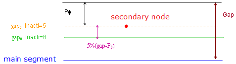
    starter_inter_type7_Inacti
    Figure 1.
  10. The sorting factor, Bumult is used to speed up the sorting algorithm.
  11. The default value for Bumult is automatically increased to 0.30 for models which have more than 1.5 million nodes and to 0.40 for models with more than 2.5 million of nodes.
  12. One node can belong to the two surfaces at the same time.
  13. There is no limitation value to the stiffness factor (but a value larger than 1.0 can reduce the initial time step).
  14. For Friction Formulation
    • If the friction flag Ifric = 0 (default), the old static friction formulation is used:

      F t μ F n with μ = Fric ( μ is Coulomb Friction coefficient)

    • For flag Ifric > 0, new friction models are introduced. In this case, the friction coefficient is set by a function μ = μ ( ρ , V )
      Where,
      ρ
      Pressure of the normal force on the main segment
      V MathType@MTEF@5@5@+= feaagKart1ev2aaatCvAUfeBSjuyZL2yd9gzLbvyNv2CaerbuLwBLn hiov2DGi1BTfMBaeXatLxBI9gBaerbd9wDYLwzYbItLDharqqtubsr 4rNCHbGeaGqiVu0Je9sqqrpepC0xbbL8F4rqqrFfpeea0xe9Lq=Jc9 vqaqpepm0xbba9pwe9Q8fs0=yqaqpepae9pg0FirpepeKkFr0xfr=x fr=xb9adbaqaaeGaciGaaiaabeqaamaabaabaaGcbaGaamOvaaaa@36D1@
      Tangential velocity of the secondary node
  15. Currently, the coefficients C1 through C6 are used to define a variable friction coefficient μ for new friction formulations.
    The following formulations are available:
    • Ifric = 1 (Generalized viscous friction law):(11)
      μ = Fric + C 1 p + C 2 V + C 3 p V + C 4 p 2 + C 5 V 2
    • Ifric = 2 (Darmstad law):(12)
      μ = C 1 e ( C 2 V ) p 2 + C 3 e ( C 4 V ) p + C 5 e ( C 6 V )
    • Ifric = 3 (Renard law):(13)
      μ = C 1 + ( C 3 C 1 ) V C 5 ( 2 V C 5 ) if V [ 0 , C 5 ]
      (14)
      μ = C 3 ( ( C 3 C 4 ) ( V C 5 C 6 C 5 ) 2 ( 3 2 V C 5 C 6 C 5 ) ) if V [ C 5 , C 6 ]
      (15)
      μ = C 2 1 1 C 2 C 4 + ( V C 6 ) 2 if V C 6

      Where,

      C 1 = μ s

      C 2 = μ d

      C 3 = μ max

      C 4 = μ min

      C 5 = V c r 1

      C 6 = V c r 2

    • First critical velocity V c r 1 = C 5 = must be different to 0 (C50).
    • First critical velocity V c r 1 = C 5 must be lower than the second critical velocity V cr 2 = C 6 ( C 5 < C 6 ) .
    • The static friction coefficient C1 and the dynamic friction coefficient C2, must be lower than the maximum friction coefficient C2 (C4C1 and C4C2).
  16. Friction Filtering
    If Ifiltr0 , the tangential forces are smoothed using a filter:(16)
    F t = α F t + ( 1 α ) F t 1
    Where α coefficient is calculated from:
    • If Ifiltr = 1 α = X f r e q , simple numerical filter
    • If Ifiltr = 2 α = 2 π X freq standard -3dB filter, with X freq = d t T and T MathType@MTEF@5@5@+= feaagKart1ev2aaatCvAUfeBSjuyZL2yd9gzLbvyNv2CaerbwvMCKf MBHbqefqvATv2CG4uz3bIuV1wyUbqedmvETj2BSbqefm0B1jxALjhi ov2DaebbnrfifHhDYfgasaacH8srps0lbbf9q8WrFfeuY=Hhbbf9v8 qqaqFr0xc9pk0xbba9q8WqFfea0=yr0RYxir=Jbba9q8aq0=yq=He9 q8qqQ8frFve9Fve9Ff0dmeaacaGacmGadaWaaiqacaabaiaafaaake aacaWGtbaaaa@39AF@ is filtering period
    • If Ifiltr = 3 α = 2 π X freq dt standard -3dB filter, with Xfreq is cutting frequency

    The filtering coefficient Xfreq should have a value between 0 and 1.

  17. Friction penalty formulation Iform
    • If Iform = 1, (default) viscous formulation, the friction forces are:(17)
      F t = min ( μ F n , F adh )
    • While an adhesion force is computed as:(18)
      F adh = C V t with C = VIS F 2 Km
    • If Iform = 2, stiffness formulation, the friction forces are:(19)
      F t new = min ( μ F n , F adh )
    • While an adhesion force is computed as:(20)
      F adh = F t old + Δ F t with Δ F t = K V t δ t

      Where, V t MathType@MTEF@5@5@+= feaagKart1ev2aaatCvAUfeBSjuyZL2yd9gzLbvyNv2CaerbwvMCKf MBHbqefqvATv2CG4uz3bIuV1wyUbqedmvETj2BSbqefm0B1jxALjhi ov2DaebbnrfifHhDYfgasaacH8srps0lbbf9q8WrFfeuY=Hhbbf9v8 qqaqFr0xc9pk0xbba9q8WqFfea0=yr0RYxir=Jbba9q8aq0=yq=He9 q8qqQ8frFve9Fve9Ff0dmeaacaGacmGadaWaaiqacaabaiaafaaake aacaWGwbWaaSbaaSqaaiaadshaaeqaaaaa@3AD7@ is contact tangential velocity.