/INICRACK
Block Format Keyword Definition of the initial crack.
Format
| (1) | (2) | (3) | (4) | (5) | (6) | (7) | (8) | (9) | (10) |
|---|---|---|---|---|---|---|---|---|---|
| /INICRACK/inicrack_ID | |||||||||
| inicrack_title | |||||||||
| node_ID1 | node_ID2 | Ratio | |||||||
Definitions
| Field | Contents | SI Unit Example |
|---|---|---|
| inicrack_ID | Initial crack identifier. (Integer, maximum 10 digits) |
|
| inicrack_title | Initial crack title. (Character, maximum 100 characters) |
|
| node_ID1 | Node identifier
1. (Integer) |
|
| node_ID2 | Node identifier
2. (Integer) |
|
| Ratio | Ratio for partitioning an element edge
(node_ID1 and node_ID2). (Real) |
Comments
- An initial crack matches with two points belonging to an element edges, points
defined as:
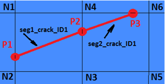
Figure 1.- The first point, P1, of the initial crack line, lies on the edge defined by nodes
(N1 and N2). The location of point P1 onto the edge (between N1 and N2) is given by
the value of Ratio.
- If Ratio = 0, the point P1 coincides with the node N1.
- If Ratio = 1, the point P1 coincides with the node N2.
- If 0 < Ratio < 1, the point P1 is located between the nodes (N1 and N2 at a distance from N1 which is the distance between N1 and N2 multiplied by the value of Ratio).
- The second point, P2, which is used to define an initial crack line segment is
introduced similarly to point P1, on one of the other edges of this same shell
element. Only one crack line segment is allowed inside one element.
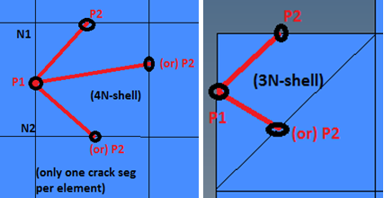
Figure 2. - To create a simple initial crack line segment, at least two pairs of nodes (N1 and N2) need to be defined.
- Crack line segments should be continuously defined. It means that, P2, the second
point in one crack segment, must be the first point, P1, of the cracks next
segment.
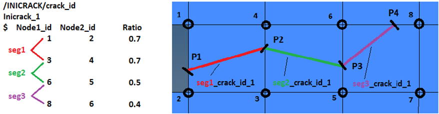
Figure 3.
- The first point, P1, of the initial crack line, lies on the edge defined by nodes
(N1 and N2). The location of point P1 onto the edge (between N1 and N2) is given by
the value of Ratio.
- /INICRACK is used to define initial cracks in 4-node and 3-node shells only.
- Multiple initial crack lines can be defined using multiple /INICRACK cards provided they never cross the same element.
- Only one crack line is allowed per element.