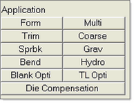
Application
|
Form
|
Lets you set up a single-stage forming analysis.
|
Multi
|
Lets you set up a multi-stage forming analysis.
|
Trim
|
Lets you set up a trimming analysis. Triggers the following buttons under the Setup grouping:
|
|
Import line
|
Imports a line that could be utilized for trimming.
|
Combine line
|
Combines two lines into a single line.
|
Trimming setup
|
Lets you set up the input parameters for a trimming analysis.
|
Coarse
|
Lets you set up a mesh coarsening analysis. Triggers the following buttons under the Setup grouping:
|
|
Remove loads
|
Removes loads and boundary conditions from a mesh.
|
Coarsen setup
|
Lets you define the input parameters for a coarsening analysis.
|
Sprbk
|
Lets you set up a springback analysis. Triggers the following buttons under the Setup grouping:
|
|
Sprbk setup
|
Lets you define the input parameters for a springback analysis.
|
Grav
|
Lets you set up a gravity analysis. Triggers the following buttons under the Setup grouping:
|
|
Autoposition
|
Automatically locates the blank on top of the tool without any penetration.
|
Contacts
|
Opens the create/edit Contact panel.
|
Gravity setup
|
Lets you define the input parameters for a gravity analysis.
|
Bend
|
Lets you set up a rotary draw tube bending. Triggers the following buttons under the Setup grouping:
|
Bending Model Creator
|
|
Bending Setup
|
Lets you define the parameters for a tube bending analysis.
|
List
|
Shows a table summarizing the attributes for different components in the model. The component attributes can be easily modified by editing this table.
|
Spherical joint
|
Creates a spherical joint.
|
Hydro
|
Setup a hydroforming analysis.
|
Import Tooling
|
|
Hydro Setup
|
Lets you define the parameters for a hydroforming analysis.
|
Constraints
|
|
|
|
Submenu of macros that help you to optimize mesh so that it follows the trim line as closely as possible.
|
TL Opti
|
Lets you trim by selecting elements or components. The trimming by components option trims only the elements inside the trim line.
|
|
|
Compensates for die springback on the blank.
|
Model
|
HF
|
Imports a HyperForm file saved in an earlier session.
|
CAD
|
Imports external CAD files. Commonly used, supported file formats include: CATIA, IGES, STL, PDGS, VDAFS, UG18 and UG_NX.
|
FE
|
Imports input decks corresponding to different FE solvers. Commonly used, supported solver formats include: OptiStruct, Nastran, ANSYS, Abaqus, LS-DYNA, RADIOSS, PAM-CRASH 2G, MoldFlow, C-Mold, etc.
|
Remove Holes
|
Identifies all pinholes < 100mm diameter on the displayed surfaces and allows you to delete them.
|
|
|
Opens the R Mesh macro.
|
B-Mesh
|
Opens the Blank Surface Meshing dialog, on which you can specify an average edge length and mesh selected surfaces.
|
|
|
Opens a completely different macro with completely different buttons.
|
Setup
|
|
|
Defines section properties, including thickness.
|
|
|
Defines material properties.
|
|
|
Lets you select materials and review the material’s properties.
|
|
|
Lets you creates tool and blank components and assign their section and material properties.
|
List…
|
Displays a table summarizing the attributes for different components in the model. The component attributes can be easily modified by editing the table.
|
Symmetry plane…
|
Lets you define the symmetry planes in a model.
|
Tool Setup
|
Lets you create and position the tools for stamping analysis.
|
Tool Motion
|
Lets you define the tool motion parameters, as well as the solution control and output history parameters.
|
Tool Load
|
Lets you define the force on a blankholder or pad, and activate a rigid body stopper.
|
|
|
Lets you define the drawbeads and the corresponding restraining forces. You can use either a line or a set of nodes to describe the drawbead location.
|
|
|
Opens the Drawbeads Editor.
|
|
|
Let you define either single or multiple contact definitions between the blank and tools.
|
Save
|
Saves your file.
|
Run
|
Launches a Dyna analysis, and also lets you select the component for which a Dyna ASCII output is required during subsequent analysis. From here, you can also get a summary of your model and a preview of the tool motion before launching the analysis.
|
|
|
Provides an easy-to-use setup for various process types. The Auto Process macro prompts you for all necessary parameters for a given analysis type.
|
|
|
Provides a convenient graphical setup for process sequences that include multiple stages of processing. It also enables you to define the parameters for each process stage.
|
Results
|
Load Results
|
Launches the post processor (HyperView) with the results for the current model.
|
Report Generator
|
Lets you create an HTML-based or PowerPoint presentation containing results from the forming analysis. Choose from among five result types and export as H3D, JPEG, or AVI files.
Note: End users viewing the report must have the HyperView Player (7.0 SP1,SA-042 and above) installed to take full advantage of the animation features in the report.
|