User Profiles:
|
Incremental_RADIOSS
Incremental_LS-DYNA
RADIOSS One Step
Die Module
|
Use the Check Elems panel to verify the basic quality of your elements, as well as the geometric qualities of those elements.
Panel Usage
The panel consists of several subpanels for different types of quality checks. Each subpanel displays checks of a specific type, depending on dimensionality, time steps, and so forth. Each check is listed on a green command button; clicking the button performs a check and the results are summarized in the status bar. In addition, many also include text fields so that you can edit the check criteria. Edited criteria are preserved even if you navigate to a different subpanel and then back again. However, criteria on different subpanels do not relate to each other, so changing the length requirement on the 1-d subpanel does not change the length requirement on the 2-d subpanel.
Many different checks are supplied to provide for the quality measurements of different types of elements. For example, if you have created a quad, it is possible that the quad has some degree of warpage. You can use the warpage function to check the element for warpage and to specify the maximum allowable warpage for that element.
Another check available is for rigid loops. Use rigid loops to determine if a group of one-dimensional rigid elements forms a loop. After it checks for instances where this has occurred, it highlights the elements that failed the test.
| Note: | HyperMesh treats second-order elements just like first-order ones for the majority of these checks. However, Jacobian and Chordal Deviation checks will return slightly different results for second-order elements than they will for first-order ones. For example, second-order elements may produce less chordal deviation, but might also produce a worse Jacobian value. See How Element Quality is Calculated for details. |
|
Subpanels and Inputs
The Check Elems panel contains the following subpanels and command buttons:
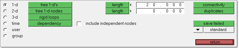
Use the 1-d subpanel to check for free ends in one-dimensional elements, to determine if a group of one-dimensional elements forms a loop, or to check rigid elements for conditions causing double dependency.
Panel Inputs
Input
|
Action
|
free 1-d's
|
Test for free ends in one-dimensional elements
|
free 1'd nodes
|
Test for free nodes (not connected to another mesh) at the ends of one-dimensional elements.
|
rigid loops
|
Check one-dimensional rigid elements for rigid loops.
One-dimensional rigid elements that build loops are highlighted. Rigid elements are detected as forming a loop if the rigid elements form a closed loop and the dependent node of one rigid serves as independent node of the next rigid in the loop.
If memory requirements are exceeded, reduce the number of displayed rigids.
|
dependency
|
Check one-dimensional weld and rigid elements for conditions causing double dependency.
|
include independent nodes
|
If this option is turned on, 1-D elements that share a node (dependent or independent) are considered to fail the check. This option is valid for some solvers such as LS-DYNA, Altair Radioss, and so on.
If this option is turned off, 1-D elements that share the same dependent node are considered to fail this check. Thus a rigid element whose dependent node is an independent node of another rigid element does not fail this check. This option is valid for some solvers such as Altair OptiStruct, Nastran, and so on.
|
length <
|
The elements that have a length less than the value specified are highlighted when the length function is selected. These elements remain highlighted until you exit the Check Elems panel or you select another check element function.
|
length >
|
The elements that have a length greater than the value specified are highlighted when the length function is selected, and remain highlighted until you exit the Check Elems panel or select another check element function.
|
|
In addition to the functions common to the Check Elems panels, use the 2-d subpanel to check elements for warpage, aspect ratio, skew, chordal deviation, and jacobian ratio. You can also check the maximum and minimum interior angles of quad and tria elements in this panel.
Panel Inputs
Option
|
Action
|
warpage
|
The amount by which an element or element face (in the case of solid elements) deviates from being planar. Warpage of up to five degrees is generally acceptable.
|
aspect
|
The ratio of the longest edge of an element to its shortest edge. Aspect ratio should be less than 5:1 in most cases.
|
skew
|
Skew in trias is calculated by finding the minimum angle between the vector from each node to the opposing mid-side and the vector between the two adjacent mid-sides at each node of the element. Ninety degrees minus the minimum angle found is reported as the skew.
Skew in quads is calculated by finding the minimum angle between two lines joining opposite mid-sides of the element. Ninety degrees minus the minimum angle found is reported.
|
chord dev
|
Test elements for chordal deviation.
|
cell squish
|
The cell squish criteria describes the non-orthogonality of an element with respect to its faces for 3D elements or edges for 2D elements. It is defined as follows:
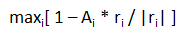
For 2D elements:
| • | Ai = unit vector, normal to cell edge i |
| • | ri = vector connecting the cell centroid and the middle of edge i. |
For 3D elements:
| • | Ai = unit area vector, normal to cell edge i |
| • | ri = vector connecting the cell centroid and the centroid of face i |
|
length >
|
The elements that have a length greater than the values specified are highlighted when the length function is selected. These elements remain highlighted until you exit the Check Elems panel or you select another check element function.
|
length <
|
The elements that have a length less than the values specified are highlighted when the length function is selected. These elements remain highlighted until you exit the Check Elems panel or you select another check element function.
|
jacobian
|
A measure of the deviation of an element from an ideally shaped element. The Jacobian value ranges from 0.0 to 1.0, where 1.0 represents a perfectly shaped element. However, Jacobian values of 0.7 and above are generally acceptable. The determinant of the Jacobian relates the local stretching of the parametric space required to fit it onto global coordinate space. HyperMesh evaluates the determinant of the Jacobian matrix at each of the element’s integration points (also called Gauss points), and reports the ratio between the smallest and the largest.
|
equia skew
|
Opens the equiangle skew utility. This utility is used to find the number of elements among those displayed that have a normalized equiangle skew larger than the value specified. The normalized equiangle skew is defined thusly:
QN: normalized angle, QE: ideal angle, QA: angle, Q: equiangular skew
If (QA < QE)
QN = (QE - QA) / QE
Else
QN = (QA - QE) / (180 - QE)
The above equation is evaluated for all angles in a shell, all angles in cell faces and all dihedral angles of neighboring cell faces (i=1…n)
The equiangle skew is defined as Q = max(QNi), i=1,n
With QA:
2D: all angles of shell
3D: all angles of cell faces as in 2D and all dihedral angles between neighboring cell faces
QE is dependent on idealization of shell/cell, which is an element with all equal sides:
Tria
|
QE = 60
|
Quad
|
QE = 90
|
Tetra
|
QE = 70.528779365509308630754000660038
|
Pyramid
|
QE = 109.47122063449069136924599933996 between tria faces or
QE = 54.735610317245345684622999669981 between quad and tria faces
|
Penta
|
QE = 90 between quad and tria faces or
QE = 60 between quad faces
|
Hexa
|
QE = 90
|
|
|
area skew
|
The area skew criterion describes the deviation of an elements with respect to an “optimal” elements.
A circle is generated through the three corner points of the actual triangle. This circle defines a ideally shaped tria elements, from which the area is computed, A_ideal. The area from the actual triangle is computed as well, A_actual. The area skew is defined as: Area skew = (A_ideal-A_actual) / A_ideal.
|
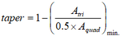
taper
|
Taper ratio for quadrilateral elements is defined by first finding the area of the triangle formed at each corner grid point:
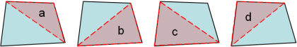
These areas are then compared to one half of the area of the quadrilateral.
HyperMesh then finds the smallest ratio of each of these triangular areas to ½ the quad element’s total area (in the diagram above, "a" is smallest). The resulting value is subtracted from 1, and the result reported as the element taper. This means that as the taper approaches 0, the shape approaches a rectangle.
Triangles are assigned a value of 0, in order to prevent HyperMesh from mistaking them for highly-tapered quadrilaterals and reporting them as "failed".
|
trias: min angle
|
The minimum allowable interior angle for a tria element. Any element for which any interior angle falls below the specified value is highlighted and remains highlighted until you exit the Check Elems panel or you select another check.
|
trias: max angle
|
The maximum allowable interior angle for a tria element. Any element for which any interior angle is greater than the specified value is highlighted and remains highlighted until you exit the Check Elems panel or you select another check.
|
quads: min angle
|
The minimum allowable interior angle for a quad element. Any element for which any interior angle falls below the specified value is highlighted and remains highlighted until you exit the Check Elems panel or you select another check.
|
quads: max angle
|
The maximum allowable interior angle for a quad element. Any element for which any interior angle is greater than the specified value is highlighted and remains highlighted until you exit the Check Elems panel or you select another check.
|
|
In addition to the element checking functions on the 2-d subpanel, use the 3-d subpanel to check tetra elements by various measures.
Panel Inputs
Input
|
Action
|
warpage
|
The amount by which an element or element face (in the case of solid elements) deviates from being planar. Warpage of up to five degrees is generally acceptable.
|
aspect
|
The ratio of the longest edge of an element to its shortest edge. Aspect ratio should be less than 5:1 in most cases.
|
skew
|
Skew in trias is calculated by finding the minimum angle between the vector from each node to the opposing mid-side and the vector between the two adjacent mid-sides at each node of the element. Ninety degrees minus the minimum angle found is reported as the skew.
Skew in quads is calculated by finding the minimum angle between two lines joining opposite mid-sides of the element. Ninety degrees minus the minimum angle found is reported.
|
tet collapse
|
Tetra elements whose collapse value falls below the value specified are highlighted when the tetra collapse function is selected. These elements remain highlighted until the Check Elems panel is exited.
HyperMesh calculates tetra collapse by the following procedure. At each of the four nodes of the tetra, the distance from the node to the opposite side of the element is divided by the square root of the area of the opposite side. The minimum value found is normalized by dividing it by 1.24, and then reported. As the tetra collapses, this value approaches 0.0. For a perfect tetra, this value is 1.0.
|
cell squish
|
The cell squish criteria describes the non-orthogonality of an element with respect to its faces. It is defined as follows:  with: with:
| • | A = face unit area vector |
| • |  = 2D elements: vector connecting the adjacent cell centroids = 2D elements: vector connecting the adjacent cell centroids |
| • | 3D elements: vector connecting the cell centroids and the cell face centroid |
|
length >
|
The elements that have a length greater than the values specified are highlighted when this function is selected. These elements remain highlighted until you exit the Check Elems panel or you select another check element function.
|
length <
|
The elements that have a length less than the values specified are highlighted when this function is selected. These elements remain highlighted until you exit the Check Elems panel or you select another check element function.
|
jacobian
|
A measure of the deviation of an element from an ideally shaped element. The Jacobian value ranges from 0.0 to 1.0, where 1.0 represents a perfectly shaped element. However, Jacobian values of 0.7 and above are generally acceptable. The determinant of the Jacobian relates the local stretching of the parametric space required to fit it onto global coordinate space. HyperMesh evaluates the determinant of the Jacobian matrix at each of the element’s integration points (also called Gauss points), and reports the ratio between the smallest and the largest.
|
equia skew
|
Opens the equiangle skew utility. This utility is used to find the number of elements among those displayed that have a normalized equiangle skew larger than the value specified. The normalized equiangle skew is defined thusly:
QN: normalized angle, QE: ideal angle, QA: angle, Q: equiangular skew
If (QA < QE)
QN = (QE - QA) / QE
Else
QN = (QA - QE) / (180 - QE)
The above equation is evaluated for all angles in a shell, all angles in cell faces and all dihedral angles of neighboring cell faces (i=1…n)
The equiangle skew is defined as Q = max(QNi), i=1,n
With QA:
2D: all angles of shell
3D: all angles of cell faces as in 2D and all dihedral angles between neighboring cell faces
QE is dependent on idealization of shell/cell, which is an element with all equal sides:
Tria
|
QE = 60
|
Quad
|
QE = 90
|
Tetra
|
QE = 70.528779365509308630754000660038
|
Pyramid
|
QE = 109.47122063449069136924599933996 between tria faces or
QE = 54.735610317245345684622999669981 between quad and tria faces
|
Penta
|
QE = 90 between quad and tria faces or
QE = 60 between quad faces
|
Hexa
|
QE = 90
|
|
|
vol skew
|
Tetra elements whose volumetric skew measurement exceeds the value specified are highlighted when the volumetric skew function is selected. These elements remain highlighted until the Check Elems panel is exited.
HyperMesh calculates volumetric skew by the following procedure. HyperMesh fits a sphere through the four nodes of the tetra. That sphere defines an ideally shaped equilateral tetra, whose volume is  . HyperMesh then calculates the actual volume of the tetra element. . HyperMesh then calculates the actual volume of the tetra element.
The element's volumetric skew is then (Videal -Vactual)/Videal. This measure will, normally, equal the skew measure from Tgrid, and equal 1 minus the equivalent check in Abaqus.
|
vol AR
|
Elements whose Vol AR measurement exceeds the value specified are highlighted when the Vol AR function is selected. These elements remain highlighted until you exit the Check Elems panel.
HyperMesh calculates Vol AR for tetrahedral elements using the following procedure: first it finds the longest edge of the tetrahedron, then it finds the shortest altitude of the tetrahedron. The element's Vol AR, then, is the length of the longest edge divided by the length of the shortest altitude. For other types of 3d element, the ratio of the longest to the shortest edge is reported.
|
tria faces: min angle
|
The minimum allowable interior angle for a tria element. Any element for which any interior angle falls below the specified value is highlighted and remains highlighted until you exit the Check Elems panel or you select another check.
|
tria faces: max angle
|
The maximum allowable interior angle for a tria element. Any element for which any interior angle is greater than the specified value is highlighted and remains highlighted until you exit the Check Elems panel or you select another check.
|
quad faces: min angle
|
The minimum allowable interior angle for a quad element. Any element for which any interior angle falls below the specified value is highlighted and remains highlighted until you exit the Check Elems panel or you select another check.
|
quad faces: max angle
|
The maximum allowable interior angle for a quad element. Any element for which any interior angle is greater than the specified value is highlighted and remains highlighted until you exit the Check Elems panel or you select another check.
|
|
Use the Time subpanel to determine the approximate minimum time step for explicit solvers based on element dimensions. Additionally, the added mass required to achieve the desired minimum time step can be displayed as a contour plot on the model.
The Time (timestep) subpanel includes columns for failure criteria and minimum values for each of several criteria. Enter the desired minimum solver timestep in the failure criteria column. When the check is performed, the calculated minimum timestep for the different element types will be displayed in the minimum value column. Rows in the table represent the different classes of elements by dimension; springs, beams, shells, solids, and thick shells.
In addition, several other controls help determine which elements are affected:
Panel Inputs
Input
|
Action
|
shells and solids, springs and beams, all types
|
Use this selector to limit the element types checked. Checks can be carried out separately for shell and solid elements, for spring and beam elements, or all element types.
|
display added mass
|
This option, when used with the assign plot display mode, will plot a contour indicating the amount of required added mass to achieve the minimum time step specified in the failure criteria.
|
all, displayed
|
Use this toggle to limit the check to those elements displayed on the screen, or all elements in the model.
|
|
Use the User subpanel to specify a template file that checks for any type of user quality. If an element does not pass the quality check, the template command *markfailed() is used. Any elements that fail (using *markfailed) are highlighted on the screen.
Panel Inputs
Input
|
Action
|
template
|
Select a template file.
|
filename
|
Select an output file.
|
all, displayed
|
Use this toggle to limit the check to those elements displayed on the screen, or all elements in the model.
|
|
The following action buttons appear throughout the subpanels:
Button
|
Action
|
connectivity
|
Tests the connectivity of a group of elements.
Two-dimensional elements that share more than one edge (two connecting nodes form an edge of a first order element; two corner nodes and one midside node form an edge of a second order element) with another two-dimensional element are highlighted.
Three-dimensional elements that share more than one face with another three-dimensional element are highlighted.
Any elements where there are mid-side nodes connected to corner nodes are highlighted.
This operator can also be used to find duplicate elements.
|
duplicates
|
Checks for duplicate elements.
If an element is duplicated, the elements involved are highlighted, except for the element with the lowest ID.
Duplicates can be deleted by selecting save failed and then retrieving the user mark (using extended entity selection) in the Delete panel. The saved (failed) elements can be accessed in any other panel using the retrieve option in the extended entity selection menu.
|
settings
|
Opens the Check Element Settings dialog.
|
save failed
|
Saves failed elements and replaces them on the user mark.
When you use this function, elements that were previously on the user mark are replaced. Once the failed elements have been saved, the user mark can be loaded into other panels.
The saved (failed) elements can be accessed in any other panel using the retrieve option in the extended entity selection menu.
|
standard, assign plot, histogram
|
Select different view modes; once chosen, activate the view by clicking the green button for the desired check:
| • | Standard is the default view; elements that exceed the specified check criteria are highlighted. |
| • | Assign Plot creates a color-coded view of the model, with each element or contour bearing a color based on how well or poorly it conforms to the selected check criterion. Visual options alters the rendering style (hidden line or wireframe), color method (by element or by contour), model lighting, and mesh line visibility. You can create a cutting plane to view a cross-section of the model. |
| • | Histogram graphs the percentage of elements on the X axis and their deviation from the specified criterion on the Y axis. A reset visual button clears the graph and returns to the model view. |
|
execute
|
Runs a check based on the template and filename specified.
Only available in the user subpanel.
|
preview unused
|
Locates and displays all interface elements defined in the model that are not attached to any normal elements.
Only available in the group subpanel.
|
deleted unused
|
Deletes all interface elements defined in the model that are not attached to any normal elements.
Only available in the group subpanel.
|
reject
|
Undoes the most recent deletion.
Only available in the group subpanel.
|
reset visual
|
Clears the histogram and returns to the normal view of the model.
Only available in the histogram view.
|
return
|
Exits the panel.
|
|
See also
Check Element Settings window
HM-3300: Checking and Editing Mesh
How Element Quality is Calculated


