|
»Click here to display Table of Contents«
|

Drawbeads Editor |

|

|

|

|
|
Drawbeads Editor |
|
|
|

|
|
»Click here to display Table of Contents«
|
Drawbeads Editor |
|
|
|
|
|
Drawbeads Editor |
|
|
|
|
The Drawbeads Editor can be started by clicking the Setup menu, or from clicking a drawbead entry in the Auto Process macro. The Drawbeads Editor helps you quickly design drawbeads from lines for an analysis. You can also work with drawbeads created from components, nodes, or geometry files.
Follow these steps in the Drawbeads Editor to create and modify drawbeads for your analysis:
| 1. | Use the |
Once you have completed the nodes, click the Create button. The line becomes yellow and an entry for a drawbead appears in the table below.
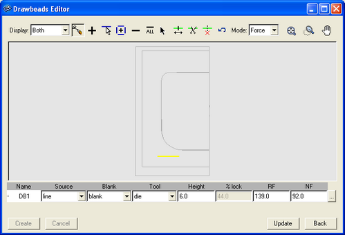
| 2. | Complete the data fields for the drawbead in the table. Specify the following items: |
Option |
Description |
||||||||
Source |
Select which type of source data you are using to define the drawbead: line, component, nodes, or geom file:
|
||||||||
Blank |
The component on which the drawbead acts. |
||||||||
Tool |
The component where the drawbead is attached. |
||||||||
Height |
The height of the drawbead. |
||||||||
% lock |
The percentage of the required necking force to apply as the force for the drawbead. |
||||||||
RF |
The restraint force. Click the … button to use the Drawbead Calculator to calculate new force values based on different model parameters. |
||||||||
NF |
The normal force. Click the … button to use the Drawbead Calculator to calculate new force values based on different model parameters. |
| 3. | Click Update to perform the drawbead calculations, draw the load curves, and project the nodes that correspond to the drawbead orientation on to the surfaces of the die. |
The following tools are available on the Drawbeads Editor toolbar.
Button |
Function |
|
In the drop-down menu, select Both to display both the drawbeads and lines in the model representation, Drawbeads to display only the drawbeads in the model representation, or Lines to display only the lines in the model representation. |
|
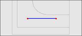
Create a drawbead by clicking points to define the line. When the points are in place, click Create to set the line and create a corresponding drawbead based on the line. |
|
Click to add a drawbead to the table. Then complete the fields for the row in the table to define the drawbead. |
|
Click lines to select them. Lines appear as blue dashes. When they are selected, they become yellow. |
|
Click to add a drawbead for each line. |
|
Click to delete the active drawbead from the table. The active drawbead in the table has a gray arrow next to it. |
|
Click to delete all drawbeads. |
|
Click on a drawbead in the model to select it. |
|
Click a drawbead to select it and then click and drag endpoints to change the size of the drawbead. |
|
Click a point on a drawbead to split the drawbead into two drawbeads at that location. |
|
Click two when the button is selected to combine them into a single drawbead. |
|
Click the button to undo the last action in the Drawbeads Editor. |
|
In the drop-down menu, select: Force to set the force calculation mode as the default, which requires that you supply values for restraining and closure forces. You can also use the Drawbead Calculator to determine values. or %-lock to set the force calculation mode as percent lock, which applies force as a percentage of the required necking force. |
|
Click to fit the model to the current window size. |
|
Zoom feature. Click once to fit the model in the window. Click and drag to draw a rectangle to zoom in on that selection area. |
|
Click and drag to move the viewing area when the model is zoomed in. |