The Advanced panel contains subpanels (gravity, springback, trimming, and coarsening) that provide users a means of performing a variety of useful operations in a multi-run setup.
Option
|
Description
|
gravity
|
Allows you to setup a gravity analysis. The primary purpose of simulating gravity is to compute the shape of the deformed sheet due to a gravity load. This can help to reduce the simulated tool travel distance, and eliminates some of the low frequency dynamic oscillation that occurs when the tools first contact the blank. Two methods are available for setup: 1) dynamic implicit gravity, and 2) explicit dynamic relaxation. The explicit dynamic relaxation method is reliable, however, solution times tend to be longer. The dynamic implicit method uses the implicit solver to obtain quick solution times.
|
sprinback
|
Allows you to setup a springback analysis.
Two springback options are available: using dynain and seamless:
| • | using dynain allows you to setup a springback analysis and apply constraints to a blank obtained from a previous forming simulation. |
| • | seamless allows you to perform a forming analysis, immediately followed by a springback analysis. For seamless, you can chose the components on which you want to apply constraints and click create. If you are using a dynain file, you can include it and then apply constraints using this panel. |
|
trimming
|
Allows you to setup a trimming operation. After a stamping simulation, mesh trimming is used to remove unwanted material from the blank. Material may be removed from either the inside or outside of the trim line. Multiple trim lines may be defined.
Two different methods are available, depending on 2D or 3D trimming in DYNA. The 2D trim option allows you to select a trim line, whereby the trim line computed as the projection is the curve onto the part surface using a single vector direction. The 3D trim option allows you to select a 3D line, whereby the trim line is computed as the closest point projection of the trim curve onto the part surface. The 3D method is very efficient, and is superior for parts trimmed at unusual angles or from multiple directions. It is assumed that the trim curve will be defined in very close proximity to the part surface.
|
coarsening
|
Used to adaptively de-refine a shell mesh by selectively merging four adjacent elements into one. Adaptive constraints are added and removed as necessary.
Coarsening is performed at the start of a simulation. By setting the termination time to zero and including the keyword *INTERFACE_SPRINGBACK_DYNA3D, a dynain file is generated containing the coarsened mesh.
An automatic search is performed, by default, to identify elements for coarsening. In some meshes, isolated regions of refinement may be overlooked. Seed nodes can be identified in these regions to assist the automatic search. Seed nodes identify the central node of a four-element group which is coarsened into a single element if the angle criterion is satisfied.
|
mapping
|
Allows you to setup the parameters required to map forming results to a crash model using the mapping algorithms of LS-DYNA. Optional mapping quantities include thickness, plastic strain, strain tensor, and stress tensor.
|
How do I...
Before setting up a gravity analysis it is necessary to have appropriately defined section and material properties for the blank and tool components. See the Materials, Section, and Components panels for more information.
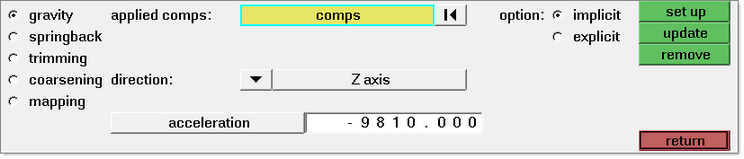
| 1. | In the Advanced panel, select gravity. |
| 2. | Select the explicit or implicit gravity setup option:. |
For the explicit option:
| a. | For applied comp:, select the blank component to which the gravity load will be applied. |
| b. | For direction:, select the direction in which the acceleration due to gravity will act. |
For the implicit option:
| a. | For applied comp:, select the blank component to which the gravity load will be applied. |
| b. | For direction:, select the direction in which the acceleration due to gravity will act. |
Note: For an improved rate of convergence, LS-DYNA 970 or better (double precision version) is required.
After setting up the gravity analysis, the contact definitions between the blank and tools must also be created. See the Contacts panel for more information.
|
Before setting up a springback analysis, you must first import the file containing the part shape, stress and strain history from a previous forming analysis for the blank. Then you must define the section and material properties for the blank component. See the Materials, Section, and Components panels for more information.
| 1. | In the Advanced panel, select springback. |
| 2. | For constraints: click nodes and select the nodes to constrain. |
|
There are two different methods available on the Trimming subpanel - 2D and 3D trimming. The 2D trim option allows you to select a trim line, whereby the trim line is computed as the projection of the curve onto the part surface using a single vector direction. The 3D trim option allows you to select a 3D line, whereby the trim line is computed as the closest point projection of the trim curve onto the part surface. The 3D method is very efficient and is superior for parts trimmed at unusual angles or from multiple directions. It is assumed that the trim curve will be defined in very close proximity to the part surface.
| 1. | In the Advanced panel, select trimming. |
| 2. | Select the 2D or 3D trimming option. |
For 2D trimming:
| a. | For trim part:, click comps and select the blank component to be trimmed. |
| b. | For trim line:, click line and select the trim line. |
| c. | All trim lines must be a single combined line. If necessary, you may have to combine lines into a single line. Multiple areas can be trimmed in a single setup by selecting multiple closed loop lines. |
| d. | For direction, select the direction to sweep the trim line. |
| e. | For trim option:, select remove element inside or remove element outside. |
For 3D trimming:
| a. | For trim part:, click comps and select the blank component to be trimmed. |
| b. | For trim lines, click line and select the trim line. |
All trim lines must be a single combined line.
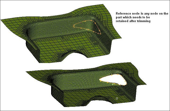
| c. | For reference: select any node on the part which is retained after trimming. Please see the image below which illustrates the functionality of reference node |
|
Before setting up a coarsening operation, a dynain file (restart file containing the part shape, stress, and strain history from a previous forming analysis) must be imported for the blank. The section and material properties must then be defined for the blank component. See the Materials, Section, and Components panels for more information. Please note that all nodal constraints must be removed prior to performing a coarsening operation on the model.
| 1. | In the Advanced panel, select coarsening. |
| 2. | Click applied comps: comps and select the blank component to be coarsened. |
| 3. | Use option autosearch to use an automatic nodal search to identify elements for coarsening. Toggle option to autosearch w/seed to perform an automatic nodal search with seed nodes (a maximum of 8 nodes can be defined). Identifying seed nodes can be effective in identifying regions that may be overlooked by the automatic search alone. |
| 4. | Enter the allowable angle change between neighborning elements. Adjacent elements are merged if the angle between them is within this allowable ange. The suggested starting value is 8.0 degrees (default). |
After setting up a coarsening operation, the *INTERFACE_SPRINGBACK card is invoked so that at the end of the computation, LS-DYNA writes out a dynain file for the component selected in step 2. This file contains the stress and strain information necessary to perform subsequent operations. The *CONTROL_TERMINATION card is turned ON and the termination time is set to zero seconds. The *DATABASE_BINARY_D3PLOT card is turned ON so that a d3plot can be viewed to evaluate the coarsening operation.
|
Before setting up a mapping operation, a dynain file (restart file containing the part shape, stress, and strain history from a previous forming analysis) should be located. This dynain file will not be read into HyperForm directly, but rather referenced as a whole, meaning it will not be partitioned into an .hmx file containing only the stress/strain information. The mesh for the crash component should be defined in HyperForm. The section and material properties must also be defined for the crash component. See the Materials, Section, and Components panels for more information.
| 1. | Select mapping in the Advanced (Incr) panel. |
| 2. | Click crash comps: comps and select the component representing the crash component. |
| 3. | Click N1 and select three nodes N1, N2, and N3 on the crash component which will be used to re-orient the crash component with respect to the stamped component. |
| 4. | Select/de-select map option: map thickness, map plastic strain, map strain tensor, or map stress tensor. |
| 5. | Click dynain file: and browse directories to find the ‘dynain’ corresponding to the stamped component. |
| 6. | Click N1S, N2S and N3S and enter the reference node ID which will be used to re-orient the stamped component with respect to the crash part. Note that the nodes selected in step 3 will be used to help re-orient reference the stamped component for mapping of the forming results. |
It is important to be aware of the following points when setting up a mapping operation using LS-DYNA.
| • | The outer boundary of the stamped and crash components do not need to match since only the regions of the crash part which overlap the stamped one are initialized. |
| • | Arbitrary mesh patterns are assumed. |
| • | Element formulations can change. |
| • | Three nodes on each part are used to re-orient the stamped part for the mapping of the forming qualities. After re-orientation, the three nodes on each part should approximately coincide. |
| • | The number of in-plane integration points can change. |
| • | The number of through-thickness integration points can change. |
| • | The node and element IDs between the stamped part and the crash part do not need to be unique. |
|
See also
Alphabetical List of Panels


