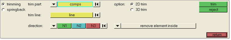
There are two different methods available on the Trimming subpanel - 2D and 3D trimming. The 2D trim option allows you to select a trim line, whereby the trim line is computed as the projection of the curve onto the part surface using a single vector direction. The 3D trim option allows you to select a 3D line, whereby the trim line is computed as the closest point projection of the trim curve onto the part surface. The 3D method is very efficient and is superior for parts trimmed at unusual angles or from multiple directions. It is assumed that the trim curve will be defined in very close proximity to the part surface.
| 1. | In the Advanced panel, select trimming. |
| 2. | Select the 2D or 3D trimming option. |
For 2D trimming:
- For trim part:, click comps and select the blank component to be trimmed.
- For trim line:, click line and select the trim line.
- All trim lines must be a single combined line. If necessary, you may have to combine lines into a single line. Multiple areas can be trimmed in a single setup by selecting multiple closed loop lines.
- For direction, select the direction to sweep the trim line.
- For trim option:, select remove element inside or remove element outside.
- Click trim.
- Click return.
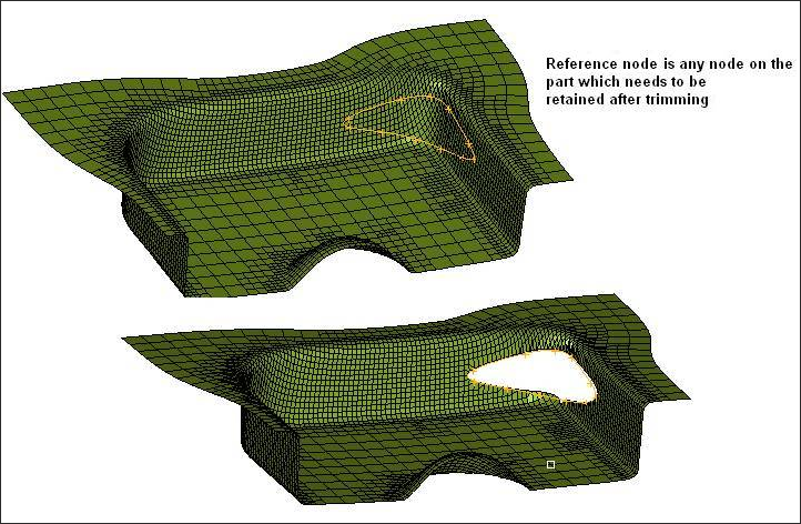
For 3D trimming:
- For trim part:, click comps and select the blank component to be trimmed.
- For trim lines, click line and select the trim line.
- All trim lines must be a single combined line.
- For reference: select any node on the part which is retained after trimming. Please see the image below which illustrates the functionality of reference node
- Click trim.
- Click return.
|