Rebuild Mesh Panel
Use the Rebuild Mesh panel to streamline the process of remeshing existing meshes to generate a new mesh with good quality and flow.
The rebuild mesh functionality utilizes the same parameter and criteria files used by BatchMesher to define the quality criteria and relevant mesh parameters. This algorithm saves significant time over the traditional automesh and quality correction approach.
- Remesh to adjust size, quality, and flow.
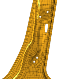
Figure 1. Before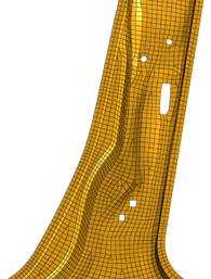
Figure 2. After - Change to a different element type.
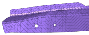
Figure 3. Before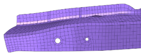
Figure 4. After - Add or remove washer layers around holes, change the nodal density of a
hole, adjust a hole diameter, or remove a hole.
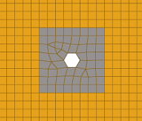
Figure 5. Before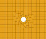
Figure 6. After - Locally correct areas with bad mesh flow.
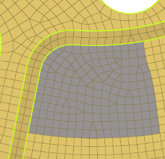
Figure 7. Before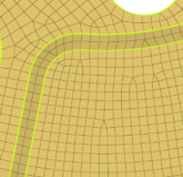
Figure 8. After
Rebuild is currently supported for first-order 2D meshes that are not attached to 3D element faces. 1D features (plot elements) are important for defining the mesh topology of FE. These features are utilized as vertices, edges and faces, in a similar way to geometry, during the rebuild operation. Such features are generated automatically by the midmesh tool, via the Features Panel, or can be manually created. If 1D features are not defined on the mesh, they will be automatically generated internally. Nodes of input elements may or may not be associated to geometry. Rebuild maintains node-geometry associativity in the regions of input mesh where the association is present.
Update several options from the parameter file to control the resulting rebuild mesh output.
Use the Edit Criteria button to open the Criteria File Editor. Here, you can set criteria options and values related to the target element size.
- Element size (Basic tab)
- Define target element size.
- Element Type (Basic tab)
- Define target element type.
- Keep selection
- Element selection is preserved for the subsequent rebuild iteration. If Always, all elements are retained. If Only Failed, only elements failed in quality and flow are retained. If Never, No elements are retained.
- Feature angle (Quality Correction tab)
- Define the feature and vertex angle used for auto generating 1D features, when required.
- Holes 2D
- Define the 2D hole table for treating circular holes.
- Move across free edges <= (Quality Correction tab)
- Define the allowable node movement for nodes on free edges to correct minimum size.
- Move across non-manifold edges <= (Quality Correction tab)
- Define the allowable node movement for nodes on non-manifold edges to correct minimum size.
- Move across shared edges <= (Quality Correction tab)
- Define the allowable node movement for nodes on shared edges to correct minimum size.
- Surface hole recognition
- Define the parameters for performing hole treatment for circular holes.