Options Panel
Use the Options panel to modify default settings in HyperWorks.
Location: Preferences menu
Geometry Subpanel
| Option | Action |
|---|---|
| cleanup tol | Clean up the CAD geometry data by equivalencing edges, deleting fillets, and eliminating extraneous vertices. Specify the cleanup tolerance value used to determine how much to modify the geometry in the course of "cleaning" it. Since you will approximate the geometry with a finite element mesh, you need to work with a cleanup tolerance that is less than the node tolerance used in the mesh generation. |
| geom feature angle | Specify the geom feature angle used to determine when model geometry should have a new vertex added (creating two surfaces from one) or removed (merging two surfaces into one). |
| geometry stitching | For panels involving
surface creation, choose how newly created surfaces are stitched
to the model.
|
| rotate angle | Specifies the amount
your model rotates when you use the rotation buttons on the
toolbar or press the arrow keys. Tip: Increasing or
decreasing the angle makes the model appear to rotate faster
or slower. For smaller models, setting the rotation angle to
a lower value desensitizes the amount of rotation and allows
a smooth transition from frame to frame.
|
| pick tol | Specifies the maximum
distance, in pixels, that the cursor can be from a graphical
entity in order to select it. Tip: When the pick
tolerance is increased, it is easier to pick an
entity.
|
| zoom factor | Specifies the multiplication factor used to increase or decrease the scale of the current view when you press the + and - keys or the zoom in/out button in the toolbar. |
| surf lines | Specifies the default
number of u-v lines to draw on new surfaces when they are
created. Tip: Displaying surface lines can help
you to visualize a surface better, but it can slow down the
redraw speed of a large model.
The number of surface
lines on existing surfaces can be changed by using the Surf
Lines panel. |
Mesh Subpanel
| Option | Action |
|---|---|
| element size | Specify a default edge length for elements, in the same units that the loaded model was created in (mm, inches, and so on). This determines the default values whenever meshing, such as in the Automesh panel. |
| element order | Choose between using first-order (corner nodes only) and second-order (corner and mid-edge nodes) elements when meshing. |
| node tol | Specify the resolution to which the finite element data in the model is maintained. When you specify a node tolerance, any two nodes are considered to be coincident if the distance between them is less than the value. |
| feature angle | Specify the maximum distance that the selected entity must be within to be included in the selection. When you select entities by face, attached adjacent surfaces or elements are progressively selected as long as the angle between them is less than or equal to the feature angle. This value is used in element cleanup. |
| topology revision | Select a method for
handling your model when the geometry's topology is changed.
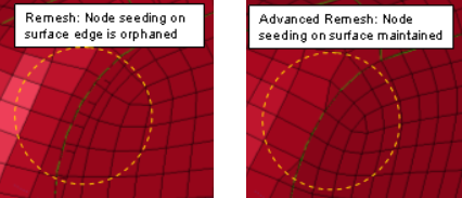 Figure 1.
|
| pick tol | Specify the maximum
distance, in pixels, that the cursor can be from a graphical
entity in order to select it. Tip: When the pick
tolerance is increased, it is easier to pick an
entity.
|
| zoom factor | Specify the multiplication factor that is used to increase or decrease the scale of the current view when you press the + and - keys or the zoom in/out button in the toolbar. |
| Allow duplicate IDs | Permit properties in
different groups to have the same ID. Note: Properties must be unique within each group. Duplicate IDs
can only exist if they are in separate groups.
Only
available in Nastran, LS-DYNA, OptiStruct and Radioss solver interfaces. |
Graphics Subpanel
| Option | Action |
|---|---|
| lights | Select a light-based shading method. |
| view simplification | To produce a smoother animation when rotating or panning a model, you can refrain the calculation and rendering of some model elements until the model stops moving. |
| simplify current comp | Apply the
simplification to the current component as well as the rest.
Clear this checkbox to retain the full detail of the
current component during view simplification.
Note: Used in
conjunction with view simplification
modes.
|
| optimize view ctrls | Remove graphical
annotations and entities when you rotate, zoom (via the mouse
wheel), or pan the model. Graphical annotations and entities are
restored once you release the mouse button. The following
graphical annotations and entities are removed:
Note: Used in conjunction with view simplification
modes.
|
| bitmap animation | Select whether to
render animation sequences as a series of 2D images instead of
full 3D modeling. Tip: For large models this can
produce faster animation, but for small ones it may actually
produce slower results.
|
| AVI Options | Select the frame size
of exported Audio-Video Interleave animation files, as a
fraction of your screen size. Use the toggle just below the switch to choose the color depth to output AVI files in: 8 bit (256 colors) or 24 bit (16.8M colors). |
| result color type | Choose between blended contours and discrete contours. |
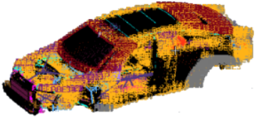
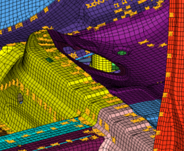
| geometry refinement | Select a geometry
refinement level to control how extensively the graphics engine
smooths faceted feature lines and contours within geometric
entities such as lines and surfaces. The degree of faceting is arbitrarily numbered from 1 to 5, with 5 being the most refined and 1 being the coarsest. Higher values may affect rendering performance. If you do not want to
continuously keep adjusting the degree of faceting, select
Auto to automatically increase
the geometry resolution when you zoom in on a model.
Note: You can set Auto as the default level of
refinement by entering the environment variable
HM_AUTO_REFINEMENT=1.
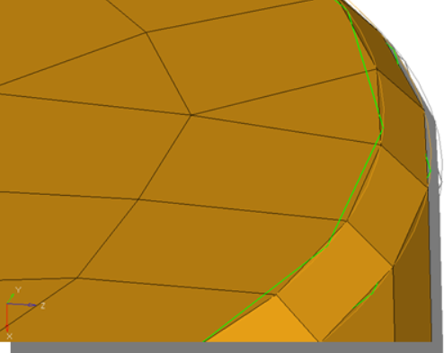 Figure 2. Lower Refinement 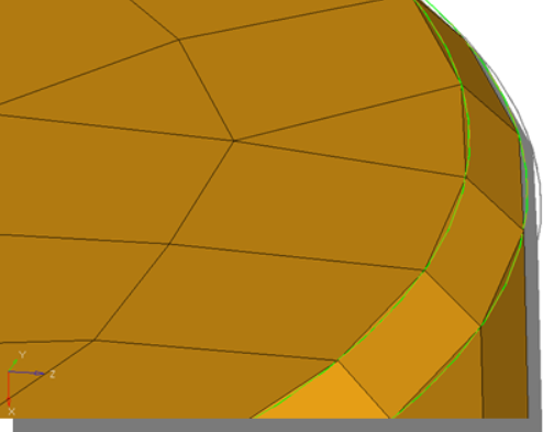 Figure 3. Higher Refinement |
| element handle | Elements are normally
drawn as simple triangles or quads. Select this checkbox to
display a small handle at each elements center, which can
sometimes aid in the selection of individual elements. However,
handles are one more item for the graphics engine to render,
therefore clearing this checkbox may improve rendering speed
when working with large models. Next to the checkbox, enter a
value from 0 to 10. This value filters out the text labels
on elements depending on how closely zoomed in the view
is.
|
| load handle | Loads, such as forces,
pressures, moments, or temperatures, normally display with a
text label indicating the type (for example, "m" for moments)
and the numeric magnitude. Clearing this checkbox to cease the
drawing of any load labels. Note: Each load panel
also has a label loads checkbox, used to toggle the display
of load magnitudes. The load handle checkbox supersedes
these, so in order for them to have any effect this checkbox
must be active.
|
| geom handle | Display handles for free lines. |
| fixed points | Display fixed
points. Clear this checkbox to turn off the display of fixed points. Note: This option does not affect the
display of free points. Fixed points can also be turned on
and off via vis opts in the Geometry Cleanup
panel.
|
| coincident picking | Select a desired
entity from a stack of coincident entities when there are
multiple entities at the same location. For example, if multiple
loads are detected at the same location, a movable pop-up
window displays containing various loads displayed
separately with their IDs turned on. You can then select the
appropriate entity. This function is activated by turning on
coincident picking in the Preferences dialog. The following
non-named entities are supported:
In addition to ID, elements, systems and loads will display type in the UI list. Named entities
display ID and color in the UI list for the entity:
The following images are an example of
coincident picking for non-named and named entities.
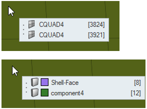 Figure 8.
 |
| shrink | Control the shrink
factor to be used when drawing elements. With zero shrink, each
element is drawn so that its corners directly connect to its
nodes. If you specify a shrink value greater than zero, the
element is scaled by the specified value about its centroid so
that its corners do not appear to touch its nodes. The shrink
value must be between 0 and 1. Tip: Shrinking
elements is useful for detecting holes in a mesh and
improving wireframe element picking.
|
| thick mesh lines | Draw mesh lines in
double the normal width for better visibility of low-contrast
colors. This option is useful when working with models that have many different components, which may cause some components to drawn in colors that do not contrast very well with the HyperWorks background. |
| Thick 1D Elements | Draws 1D elements in
double the normal width for better visibility. Note: Using thick mesh lines at the same time as thick 1D
elements may effectively negate this feature, since both
types of lines will be drawn in identical
thickness.
|
| 1D at Centroid | Drives the display of
the beam section 3D representation either at its Centroid (on)
or its Shear Center (off). If off, HyperMesh represents the 3D detailed view with GRID at the section's shear center. |
| template labels (type) | Display element labels
as template names (based on the current solver
interface). Clear this checkbox to display element labels as HyperWorks names. |
| rotate about mode | Rotate the model
around the center of all current visible entities. Clear this
checkbox to rotate the model around the center of the
screen.
Note: The different behaviors can only
be seen, when the model is not positioned in the center
of the screen.
|
Menu Config Subpanel
| Option | Action |
|---|---|
| macro file | Specify the desired macro file when using a Utility menu (activated via the View menu). |
| exponential | Display numeric fields in the panels and card editor using an exponential format. Clear this checkbox to display numeric fields using a fixed decimal format. |
| graphic font | Select a font to use when entity IDs, 1D element handles, and legends are displayed. The current font size is displayed. |
| cursor size | Choose a cursor size. |
Colors Subpanel
Use the Colors subpanel to select colors for the global axis, axis labels, free edges, suppressed edges, and T-joint edges, and many more entities. You can also change the screen background color, the global axes indicators, and more.
To change the colors of any part of the interface, click the color button next to its name and select your desired color.
| Option | Action |
|---|---|
| background | Select a background color for the modeling window. |
| global X axis | Select a color for the
X axis indicator in the global coordinate system which displays
in the corner of the modeling window.
Note: When set to background, all three axes
change to the background color on the assumption that the
only reason to make one axis invisible is to make them all
invisible for screenshots or display
purposes.
|
| global Y axis | Select a color for the
Y axis indicator in the global coordinate system which displays
in the corner of the modeling window.
Note: When set to background, all three axes
change to the background color on the assumption that the
only reason to make one axis invisible is to make them all
invisible for screenshots or display
purposes.
|
| global Z axis | Select a color for the
Z axis indicator in the global coordinate system which displays
in the corner of the modeling window.
Note: When set to background, all three axes
change to the background color on the assumption that the
only reason to make one axis invisible is to make them all
invisible for screenshots or display
purposes.
|
| axis label | Select a color for the X, Y, and Z letters on the global coordinate system which displays in the corner of the modeling window. |
| mesh line | Select a color for the
lines on a mesh that indicate the edges of mesh elements. By
default, mesh line is set to auto, which assigns the
component color as the mesh line color. To select a custom
mesh line color for the entire mesh, click the toggle.
Note:
|
| Option | Action |
|---|---|
| free edges | Select a color for the edges of surfaces that do not connect to any other surfaces. |
| shared edges | Select a color for the edges of surfaces that connect to one other surface. |
| suppressed edges | Select a color for shared edges that have been manually suppressed so that the automesher will treat the shared surfaces as if they were one surface, allowing elements to cross the edge as if it were not there at all. |
| t-junctions | Select a color for edges shared by three or more surfaces. |
| Option | Action |
|---|---|
| fin faces | Select a color for fin faces, which are surfaces that split a 3D solid entity, but only partway through, they do not actually extend through the entire entity. |
| bounding faces | Select a color for the outer faces of solid entity. |
| full partition faces | Select a color for the faces of adjoined solids |
| 2d faces (topo) | Select a color for the 2D faces that are not part of a solid when using the by 2D topo visualization mode. |
| ignored (topo) | Select a color for the 2D faces when using the by 2D topo visualization mode. |
| edges (comp) | Select a color for the mesh edges when coloring mesh with the by comp visualization mode. |
| Option | Action |
|---|---|
| ignored map | Select a default visualization color for solids that require partitioning to become mappable. |
| not mappable | Select a default visualization color for solids that have been edited, but still require further partitioning to create mappable solids. |
| 1 dir. map | Select a default visualization color for solids that can be mapped (for 3D meshing) in one direction. |
| 3 dir. map | Select a default visualization color for solids that can be mapped (for 3D meshing) in three directions. |
| Option | Action |
|---|---|
| elems, no prop/mat | Select a color to display elements that do not have any properties or materials assigned to them. |
Page Names Subpanel
- Select the page name or abbreviation you want to change.
- Enter the new name or abbreviation.
- Click return.
Graphics File Subpanel
| Option | Action |
|---|---|
| blank background | Omit the background color gradient (replacing it with flat white). |
| jpeg quality | Set the desired blend between small file size (left) and high image quality (right). |
| save JPEG | Create JPEG captures of the modeling window so that you can test and see the results of your current settings. |
| print when done | Automatically send the image to your default printer whenever a screen capture is performed. |
| AVI options | Choose the video
resolution relative to your current desktop resolution (full
screen, 1/4 screen, or 1/9 screen). You can also choose between creating videos using 8 bit color (256 total colors, resulting in smaller file size but possibly lower image quality) or 24 bit color (16.8 million colors for maximum image quality, but larger file size). Note: Only valid
for Audio-Visual Interleave videos.
|