Lines Panel
Use the Lines panel to create lines using a wide variety of methods.
Location: Geom page
The Lines panel is organized into many subpanels. Each subpanel is accessed from a toolbar-like row of buttons along the top of the panel. In some cases, a single button can access more then one subpanel; this is indicated by the presence of a small downward arrow (⏷) beside the button. Clicking this arrow reveals a list of possible functions for that button.
On any given subpanel, most of the panel is devoted to options that determine the basis from which the line will be created, whether this is a series of nodes or points, existing lines, surfaces, or mesh features. In all cases the lines are generated by using the green command buttons on the leftmost edge of each subpanel; in most cases these buttons are create and reject, but in some cases they are drag or offset buttons. In all cases, clicking reject undoes the most recent line creation.
Numeric input data, toggles, and switch settings are generally preserved even if you change subpanels or leave the Lines panel altogether; when you return, the settings remain. However, entity selections such as node or line list collectors are cleared when you switch subpanels or return out of the panel.
 xyz Subpanel
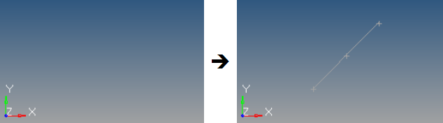
Figure 1. Line Created by X,Y,Z Coordinates. The coordinates are 3,3,3 for the start point and 8,8,8 for the end point.
- Manually enter the coordinate values into the input boxes.
- Populate individual coordinate values using the x, y and z collectors and
selecting a node graphically.
When using each of these collectors, the respective x, y, or z coordinate value is copied from the selected node into the corresponding input box. The values can be edited as desired.
- Populate the coordinate values using the as node collector and selecting a node graphically. This will copy the respective x, y and z coordinate values from the selected node into the corresponding input boxes. The values can be edited as desired.
 Linear Nodes Subpanel
Use the Linear subpanel to create linear lines between nodes.
- Node list
- Select the nodes to use.
- A straight line segment is created between each node in the list.
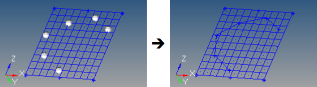
Figure 2. - Closed line
- Define whether the first and last nodes in the list should be linked to
form a closed line loop.
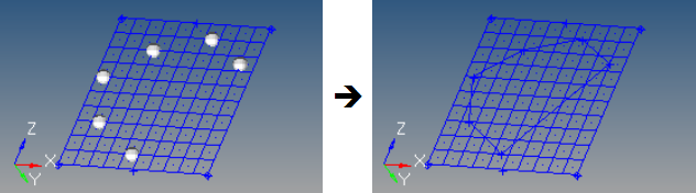
Figure 3.
 Standard Nodes Subpanel
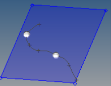
Use the Standard subpanel to create standard lines between nodes, with the possibility of reducing the number of joints and removing some nodes that fall outside of the line's path. The settings for determining joint creation and node removal are preset.
- Node list
- Select the nodes to use.
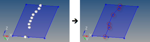
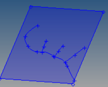
Figure 4. . Nine input nodes are simplified to six points, through which the line is fit. - Closed line
- Define whether the first and last nodes in the list should be linked to
form a closed line loop.
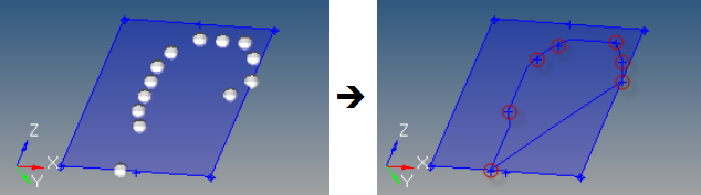
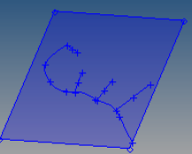
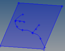
Figure 5. . Thirteen input nodes are simplified to seven points, through which a closed line loop is fit.
- break angle
- Set to 150.0 degrees.
- aspect
- Set to 5.0.
- linear angle
- Set to 179.0 degrees.
 Smooth Nodes Subpanel
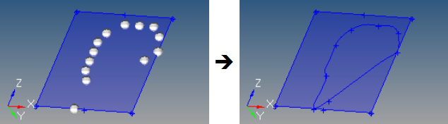
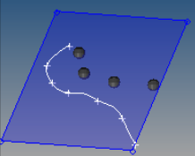
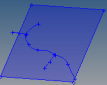
Figure 6. . Thirteen input nodes are simplified to seven points, with smooth (curved) lines fit through them.
- Node list
- Select the nodes to uses.
- Closed line
- Define whether the first and last nodes in the list should be linked to form a closed line loop.
- Start slope
- Define the line start point constraint. This option does not apply if
the closed line option is enabled.
- If set to free, this end point is not constrained.
- If set to normal, this end point is normal to the specified vector.
- If set to vector with tangent to vector selected, this end point is tangent to the specified vector.
- If set to vector with length selected, this end point parametric derivative equals the input vector, assuming a normalized spline parameterization from 0 to 1.
- End slope
- Define the line end point constraint. This option does not apply if the
closed line option is enabled.
- If set to free, this end point is not constrained.
- If set to normal, this end point is normal to the specified vector.
- If set to vector with tangent to vector selected, this end point is tangent to the specified vector.
- If set to vector with length selected, this end point parametric derivative equals the input vector, assuming a normalized spline parameterization from 0 to 1.
A smooth cubic line is created which fits through all of the specified nodes and has the specified start and end slope.
 Controlled Nodes Subpanel
Use the Controlled Nodes subpanel to specify the values that determine joint creation or node reduction.
This subpanel creates controlled lines between nodes, with the possibility of reducing the number of joints and removing some nodes that fall outside of the line's path. The settings for determining joint creation and node removal are user-specified.
- Node list
- Select the nodes to use.
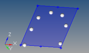
Figure 7. - Closed line
- Define whether the first and last nodes in the list should be linked to
form a closed line loop.
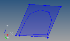
Figure 8. - Break angle
- Specify the minimum angle allowed between three points in a line. If the
angle between a point and the two adjacent points is less than the angle
specified, this point is considered to be a point of discontinuity in
the line and a joint is placed at that location.
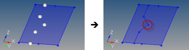
Figure 9. . Break angle is set to 150 degrees; the highlighted angle is closer to 100 degrees, therefore a joint is created. - Aspect
- Specify the maximum ratio allowed for the distance between a point and
the previous point in the line, and the distance between the same point
and the next point in the line. If the ratio of the distance between the
two adjacent segments exceeds the aspect ratio defined, a joint is
placed between the segments.
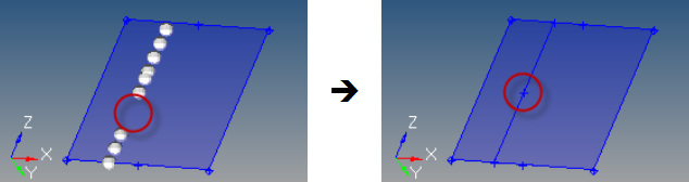
Figure 10. . Aspect is set to 5, the large gap (left) results in a joint (right) because it is more than 5 times the length of its neighbors - Linear angle
- Define the angle at which a line is considered a straight line. If the
line angle between three consecutive points along the line is greater
than the angle specified, the center point is removed from the line.
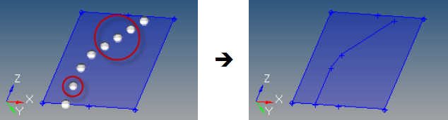
Figure 11. . Highlighted nodes are removed because they form lines with their neighbors that are greater than the linear angle setting.
A controlled line is created by performing point reduction with the specified parameters.
 Drag Along Vector Subpanel
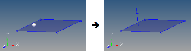
Figure 12. . input node is dragged along the Y axis in the positive direction.
- Nodes
- Select the nodes to drag.
- Vector
- Select a vector defining the direction to drag the node.
- Distance
- Define the length of the line. This can either be provided directly, or when using the N1/N2/N3 vector definition, by using the distance between N2 and N1.
- Drag direction
- Define the drag direction.
- Drag +
- Define using the specified vector direction.
- Drag -
- Define in the opposite direction.
A line is created at each node by dragging the nodes the specified distance along the given vector.
 Arc Center and Radius Subpanel
Use the Arc Center and Radius subpanel to create arcs by specifying the center and radius. It can create multiple arcs in a single operation.
- Node list
- Select each arc center. An arc is created around each node in the list.
- Plane
- Select the plane. Each node in the node list is used as a base node for the plane and the arc is created on that plane.
- Radius
- Specify the radius of each arc. The radius is measured from each node in the node list.
- Offset
- Specify the offset of each arc. This is an initial offset rotation for the start point of the arc. It is measured from the x-axis of the plane using the right-hand rule.
- Angle
- Specify the angle of each arc. This is the total angle of the arc. It is
measured starting from the offset angle using the right-hand rule.
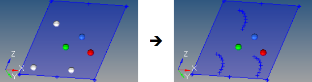
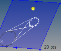
Figure 13. . The node list (white) sets the arc centers; the green (N1), blue (N2), and red (N3) nodes indicate both the direction of the arc and the plane. This particular example uses a radius of 2, an offset of 15 degrees, and a total arc angle of 90 degrees.
 Arc Nodes and Vector Subpanel
Use the Arc Nodes and Vector subpanel to create arcs by specifying two nodes and a vector. It can create multiple arcs in a single operation.
- Node list
- Define a location on each arc center. A separate arc is created through each node in the list.
- Vector
- Define the plane whose normal runs through the center of the arcs and parallel to the plane in which they lie. The base node of the vector defines the arc center.
- Offset
- Specify the offset of each arc. This is an initial offset rotation for the start point of the arc using the right-hand rule.
- Angle
- Specify the angle of each arc. This is the total angle of the arc. It is
measured starting from the offset angle using the right-hand rule.
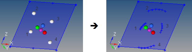
Figure 14. . This example uses four nodes, an offset of 15 degrees, and an arc angle of 45 degrees (nodes and arcs are numbered for reference).
 Arc Three Nodes Subpanel
Use the Arc Three Nodes subpanel to create arcs by specifying three nodes on the circumference.
Three nodes on the circumference are required to create an arc using this method. The first node defines the start point of the arc and the third node defines the end point of the arc. If more than three nodes are selected, only the first three are used.
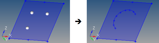
Figure 15. . A single arc is created to fit through the selected nodes.
 Circle Center and Radius Subpanel
Use the Circle Center and Radius subpanel to create circles by specifying the center and radius. Multiple circles can be created in a single operation.
- Node list
- Define a location for each circle center. A circle is created around each node in the list.
- Plane
- Define a plane. Each node in the node list is used as a base node for the plane and the circle is created on that plane.
- Radius
- Specify the radius of each circle. The radius is measured from each node in the node list.
- Offset
- Specify the offset of each circle. This is an initial offset rotation
for the start point of the circle. It is measured from the x-axis of the
plane using the right-hand rule.
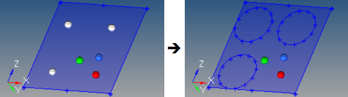
Figure 16. . The three input nodes each receive a circle with a radius of 2 on the plane defined by the N1 (green), N2 (blue), and N3 (red) nodes.
 Circle Nodes and Vector Subpanel
Use the Circle Nodes and Vector subpanel to create circles by specifying two nodes and a vector.
- Node list
- Define a location on each circle. A circle is created through each node in the list.
- Vector
- Define a plane whose normal runs through the center of the circles and parallel to the plane in which they lie. The base node of the vector defines the circle center.
- Offset
- Specify the offset of each circle. This is an initial offset rotation
for the start point of the circle using the right-hand rule.
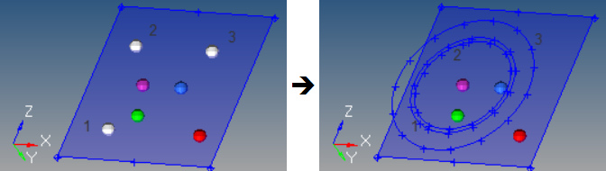
Figure 17. . The input nodes (white) each receive a circle that passes through them, but is centered on the vector's base node (purple). The N1 (green), N2 (blue), and N3 (red) nodes define the plane on which the circles lie. The outermost circle results from node 3, the middle one from node 1, and the innermost one from node 2.
 Circle Three Nodes Subpanel
Use the Circle Three Nodes subpanel to create circles by specifying three nodes on the circumference.
Three nodes on the circumference are required to create a circle using this method. If more than three nodes are selected, only the first three are used.
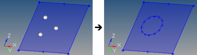
Figure 18.
 Conic Subpanel
Use the Conic subpanel to create conic lines by specifying the start, end and tangent locations.
- Start point
- Specify coordinates for the start point.
- End point
- Specify coordinates for the end point.
- Tangent point
- Specify coordinates for the tangent point, which indicates the point of intersection between straight lines tangent to the created conic curve segment the at start and end points.
- Ratio value
- Specify the ration value that defines the created conic curve segment “altitude”. Consider the segment that connects the tangents’ intersection point with the midpoint between the start and end points of the curve. If the length of this segment is used as the unit length, then the ratio is defined as the length of the portion of the segment that connects the midpoint with the point where the segment is intersected by created curve. Valid values are in the range 0 to 1. For a ratio of 0.5, the conic curve is a parabolic segment. For values between 0 and 0.5, the conic curve is an ellipse. For values between 0.5 and 1, the conic curve is a hyperbolic segment.
- A ratio of -1 can also be used to create a circular arc, provided the
length of the tangent segments are equal.
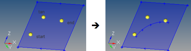
Figure 19. . Three pre-existing nodes used as input via the as node option for the criteria as labeled in the left image.
 Extract Edge Subpanel
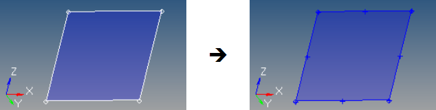
Figure 20. . Notice the point markers (+) on the corners and edges in the second image; these lie at the ends and midpoints of the created lines.
- Line/Surface
- Select a line or surface to copy.
- Create in
- Choose a method for organizing the resulting lines.
- current component
- Organize new lines in the current component.
- original component
- Organize new lines in the same component to which the selected lines or surfaces belong.
 Extract Parametric Subpanel
Use the Extract Parametric subpanel to create lines at parametric locations on surfaces.
- Surface
- Select a surface that the parametric values are in reference to.
- Create in
- Choose a method for organizing the resulting lines.
- current component
- Organize new lines in the current component.
- surf component
- Organize new lines in the same component to which the selected surfaces belong.
- Lower u bound
- Specify a value that >= 0.0.
- Upper u bound
- Specify a value that is <= 1.0.
- Number of u lines
- Specify the number of lines created between the lower and upper u bounds.
- Lower v bound
- Specify a value that is >= 0.0.
- Upper v bound
- Specify a value that is <= 1.0.
- Number of v lines
- Specify the number of lines created between the lower and upper v bounds.
- If specified > 2, lines are created at linear intervals between the
lower and upper v bounds.
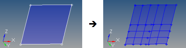
Figure 21. . This example uses a range of 0 to 0.75 with 5 u lines, and a range of 0 to 0.5 with 4 v lines.
 Intersect Subpanel
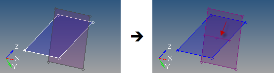
Figure 22. . This example uses plane/plane intersection; the planes are set to wireframe geometry and transparent mesh to show the resulting line.
- Geometry type
- Select the type of geometry to intersect.
- Smooth lines
- For plane/line intersections, smooth lines determines whether linear segments are created, or whether smooth curves are created.
- Line segments
- For plane/elems intersections, create a separate line segment for each
element. The combine lines option creates single line segments that are
combined from the separate segments based on the break angle and smooth
lines options.
- Break angle
- Specify where the intersection line will remain segmented. Segments with an angle relative to each other that exceed this angle will not be combined and will remain separate line segments.
- Smooth lines
- Create smooth curves within each line segment. The angles between different segments are still not smoothed, but angles less than the break angle are smoothed because segments within the break angle tolerance are combined into a single line segment.
 Manifold Subpanel
Use the Manifold subpanel to create linear and smooth lines on surfaces using nodes.
- Surface
- Select the surface that the lines will lie on.
- Node list
- Define the nodes on the surface through which the line will be created. The order of the nodes determines the path of the line.
- Trim input surface
- Specify if free lines are created or if the input surface is
trimmed.
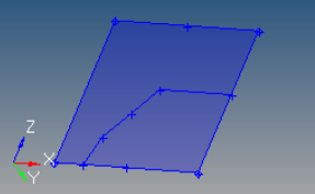
Figure 23. . Free lines are coincident with the surface. The surface is not modified.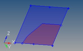
Figure 24. . Surface has been split into two different surfaces, one of which is recolored for this example. - Create in
- Choose a method for organizing the resulting lines.
- current component
- Organize new lines in the current component.
- surf component
- Organize new lines in the same component to which the selected surfaces belong.
- Line type
-
- Linear
- Create straight line segments between each input node.
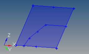
Figure 25. - Linear closed
- Create straight line segments between each input node as
well as between the first and last nodes in the list,
thereby closing the loop.
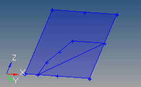
Figure 26. - Smooth
- Create a smooth line between the input nodes.
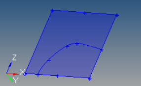
Figure 27. - Smooth closed
- Create a smooth line between the input nodes, including
closing the loop using the first and last nodes.
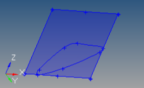
Figure 28.
 Offset Subpanel
Use the Offset subpanel to create lines by offsetting existing curved lines by a uniform or variable distance.
- Line list
- Select the line list to offset.
- Create in
- Choose a method for organizing the resulting lines.
- current component
- Organize new lines in the current component.
- surf component
- Organize new lines in the same component to which the selected lines belong. The result is unpredictable if lines from different components are used as input.
- Distance
- Define the length to offset the line along its normal.
- Uniform
- Offset the line list a uniform distance.
- Variable
- Offset the line list linearly based on a start and end offset value.
- Switch start point
- The start of the line list is indicated by the end of the chain that has
the arrow after selecting the lines, but can be reversed using this
option.
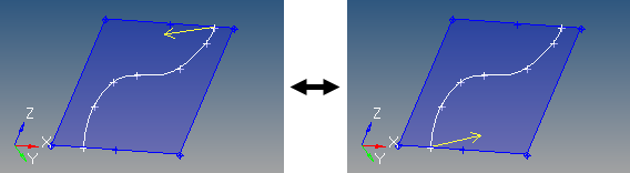
Figure 29. - Link type
- Choose how the offset is generated when there is a discontinuity (other
than 180 degrees) in the direction of the curvature of the input line
list, that is, when input lines do not connect with each other.
- interpolate
- Interpolate the offset direction on both sides of the
discontinuity to allow a smooth transition. In this case,
along the interpolation region, the offset direction will be
different than the curvature direction. Amplified
fluctuations, which would occur in the offset because of
small ripples in the input curve, are smoothed out with this
option.
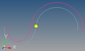
Figure 30. - insert link
- Insert a straight line segment as a link between the offset
of input lines, if there is a jump in offset direction at
points where the input lines meet.
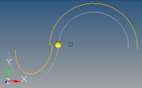
Figure 31. - no link
- Do not insert a link if there is a jump in offset direction
at points where input lines meet. In this case, the offset
lines may become disconnected.
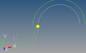
Figure 32.
- Offset direction
- Choose the direction to offset.
- offset+
- Based on the curvature of the selected lines and is shown by an arrow at the start of the line list.
- offset-
- Defined in the opposite direction.
Closed lines are treated as if they were not closed so that the offset creates open lines.
Successive offsets (4-5 offsets, one after other) or very large offset values of some lines become sensitive to approximation errors or invisible fluctuations in the line.
 Midline Subpanel
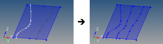
Figure 33.
- Select a line list to use for the first side.
- Select a line list to use for the second side.
The result depends on the order of the input lines selection. If the shorter of the two line segments is input as the first list and the longer one as the second, the midline is generated with a length similar to the shorter line. In addition, the midline is created only between the first line segment and a portion of the second line segment.
If the longer line segment is input as the first selection, the length of the midline generated is an average of the two line lengths.
 Fillet Subpanel
Use the Fillet subpanel to create and delete fillet lines between free lines.
- 1st line
- Select the first line to fillet.
- 2nd line
- Select the second line to fillet.
- Radius
- Specify the radius of the fillet.
- Trim original lines
- Specify whether the original input lines are trimmed by the new
fillet.
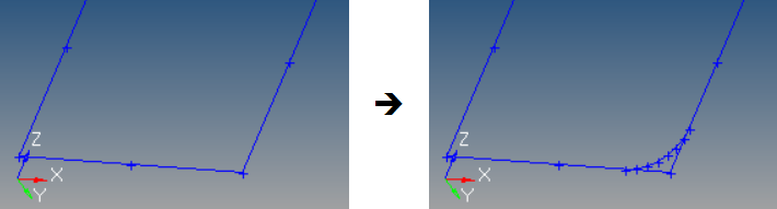
Figure 34. . When trim original lines is not active, the corner formed by the input lines remains.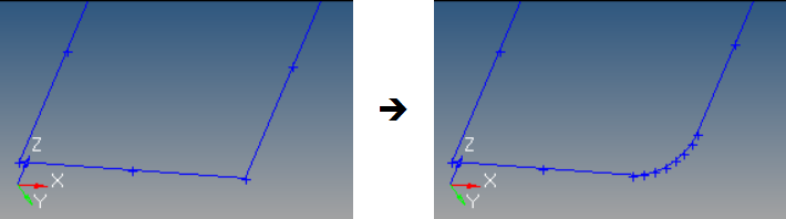
Figure 35. . When trim original lines is active, the input lines are trimmed to the start and end of the fillet.
When creating a fillet, the two closest end points are found and the tolerance between them is checked (geometry cleanup tolerance). If the two end points are within the tolerance, the radius must be greater than zero in order to create a fillet. If the two end points are not within the tolerance, and the radius is equal to zero, the closest end points of both lines are extended to their point of intersection, if such a point exists.
If the two selected lines contain at least one curved line, the fillet may not always be placed in the correct quadrant.
If the lines intersect, but not at their end points, the quadrant options are graphically displayed via a set of cross hairs. Pick the appropriate quadrant with the left mouse button.
If the two selected lines intersect in more than one place, the first intersection point is used.
For circular curves, if the arc is smaller than 180 degrees there are no issues. However, if the arc is closer to 360 degrees there may be problems. The algorithm only considers the start and end points of the circular curve to determine where to place the fillet with respect to the selected quadrant. To solve this problem, the curve should be split into segments that are longer than the second line but smaller than 180 degrees in angle of rotation.
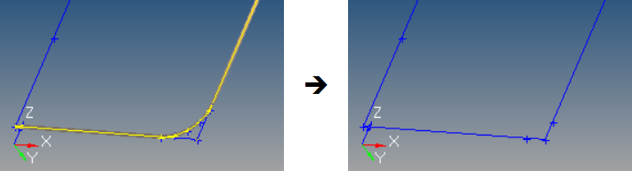
Figure 36.
 Tangent Subpanel
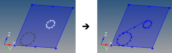
Figure 37. Tangent Created between Two Lines
- Node list
- Define the tangent origin, or the line that defines the first arc. If
multiple nodes are specified for the node list, only the first node is
used.
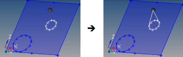
Figure 38. Tangents Created between a Node and a Line - Line
- Define the second arc.
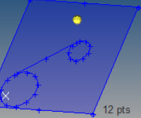
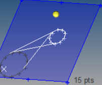
- Check points
- Specify the number of check points to use within each line segment for
finding tangents. If the desired tangent is not found, increase the
value.Figure 39. Example: Check Points
The selected nodes/lines must lie on a plane.
If more than one tangent is found, all the tangent lines found are displayed, and the desired tangent line can be graphically selected.
 Normal to Geometry Subpanel
Use the Normal to Geometry subpanel to create lines perpendicular to existing lines, surfaces and solids from node or point locations.
- Lines/Surfaces/Solids
- Select the lines/surfaces/solids to create the lines perpendicular to.
- Nodes/Points
- Select the nodes/points that define the starting point locations for the perpendicular lines.
- Create normal lines only
- Create only perpendicular lines between the node/point and the closest input geometry. No line is created if it would not be perpendicular to the nearest point on the input line.
- Clear this checkbox to create the lines between the node/point and the
closest input geometry. Lines are not guaranteed to be
perpendicular.Figure 40. . This sequence shows the difference due to the normal lines only option from the same starting point; left is the input,middle is the result with the option off, and right is with the option on (note that the uppermost node does not create a line because the nearest possible connection point would not be normal to the curved input line).
- Create in
- Choose a method for organizing the resulting lines.
- current component
- Organize new lines in the current component.
- input component
- Organize new lines in the same component to which the selected lines/surfs/solids belong. The result is unpredictable if geometry from different components are used as input.
A line segment is created for each point/geometry combination.
 Normal from Geometry Subpanel
Use the Normal from Geometry subpanel to create lines perpendicular from node or point locations on lines, surfaces and solids.
- Lines/Surfaces/Solids
- Select the lines/surfaces/solids to create the lines perpendicular from.
- Nodes/Points
- Select the nodes/points that define the starting point locations for the perpendicular lines. These must be attached/associated to the input geometry.
- Create in
- Choose a method for organizing the resulting lines.
- current component
- Organize new lines in the current component.
- input component
- Organize new lines in the same component to which the selected lines/surfs/solids belong. The result is unpredictable if geometry from different components are used as input.
- Length
- Specify the length of the lines to create at each location.
- Normal line direction
- Define the direction of the normal line.
- Normal+
- Positive normal direction at each node/point location on the geometry.
- Normal-
- Opposite direction.
 |
 |
 |
 Normal 2D on Plane Subpanel
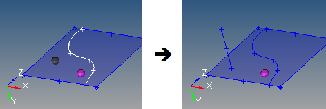
Figure 42. . The line is created at the input point, normal to the nearest spot on the line, and (in this case) along the plane for which the Z-axis is the normal (in other words, the X/Y plane).
- Node/Point
- Select the node/point that defines the starting point location for the perpendicular line.
- Line
- Select the line to create the line perpendicular to.
- Create in
- Choose a method for organizing the resulting lines.
- current component
- Organize new lines in the current component.
- input component
- Organize new lines in the same component to which the selected lines/surfs/solids belong. The result is unpredictable if geometry from different components are used as input.
- Plane
- Define a plane. The new line will lie onn this plane.
- Length
- Specify a length of the line to create.
- Normal line direction
- Define the direction of the normal line.
- Normal+
- Positive normal direction at each node/point location on the geometry.
- Normal-
- Opposite direction.
The new line has the specified length, is within the specified plane, is perpendicular to the specified line, and starts near the specified node/point.
 Features Subpanel
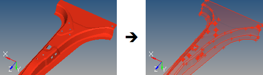
Figure 43. . In the second image, the elements are set to transparent so that the newly created lines are clearly apparent.
- Elems/Comps
- Select the elems/components to use as input. If components are selected, the elements in the component are used.
- Ignore normals
- The direction of the shell face normals are ignored and a feature line is created between any two shell faces whose normals are more than the specified feature angle or less than its inverse (the feature angle minus 180 degrees).
- Feature angle
- Specify the maximum angle to allow between the normals of two connected shell elements. When the angle exceeds this value, a feature line is generated.
- Break angle
- Specify the minimum angle allowed between three points in a line. Line joints will be created whenever the line exceeds this angle.
- Smooth lines
- Smooth lines.