Surfaces Panel
Use the Surfaces panel to create surfaces using a wide variety of methods.
Location: Geom page
 Square Subpanel
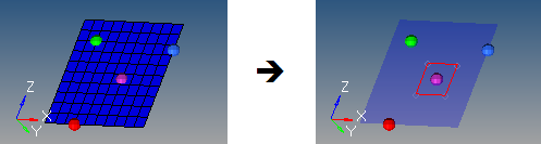
Figure 1. . A 10x10 mesh that has a new surface created with size 3 centered on the base node; the mesh is set to transparent in the second image for visibility.
| Option | Action |
|---|---|
| plane and vector selector | Define the plane in which the square surface lies, including
the base node located at the square center. If a vector is
specified, it defines the surface normal. Note: Because you are
required to select nodes, suitable nodes must already exist
in your model or a mesh from which you can select nodes. The
Square subpanel does not contain any tools to create new
nodes.
|
| size | Specify the size, indicating both the total length and width. Remember that these dimensions will be centered on the base node, therefore the resulting square will extend half this value away from it in each direction. |
 Cylinder Full Subpanel
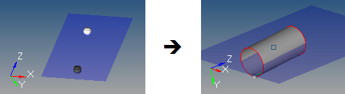
Figure 2. . The mesh is set to transparent, and geometry is set to solid with feature lines. The highlighted point is the normal vector, and extends further from the (gray) bottom center than the height.
| Option | Action |
|---|---|
| bottom center | Select the node that defines the center of the bottom cylinder face. |
| normal vector | Select the vector between the bottom center node and the normal vector node that is the cylinder axis, thereby defining the cylinder orientation. This does not indicate the actual cylinder height. |
| Base radius | Specify the radius for the top and bottom cylinder faces. |
| height | Specify the cylinder height. |
 Cylinder Partial Subpanel
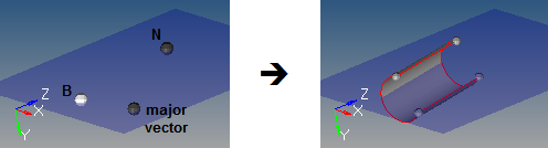
Figure 3. . This example uses Base 1, Height 4, Start Angle 30, End Angle 270, and Axis Ratio 1.
| Option | Action |
|---|---|
| bottom center | Select the node that defines the center of the bottom cylinder face. |
| normal vector | Select the vector between the bottom center node and the normal vector node that defines the cylinder axis, thereby indicating the cylinder orientation. This does not indicate the actual cylinder height. |
| major vector | Select the vector between the bottom center node and the major vector node that determines the zero-degree point of an arc defining the curved surface of the partial cylinder. This arc extends in a direction based on the normal vector using the right-hand rule, with its start angle and end angle specified relative to this vector. |
| Base radius | Specify the radius of the top and bottom cylinder faces. |
| Height | Specify the cylinder height. |
| Start angle | Specify the starting arc angle, measured from the major vector node in a direction based on the normal vector using the right-hand rule. |
| End angle | Specify the ending arc angle, measured from the major vector
node in a direction based on the normal vector using the
right-hand rule. The difference between this and the start angle determines the arc of the partial cylinder, and therefore the arc of the cutout in the partial cylinder. For example, if your start angle is 15 degrees, and your end angle is 285 degrees, the resulting cylinder has a base with a 270 degree arc and a 90 degree cut. |
| Axis ratio | Specify a percentage of the major vector. This value must be greater than zero and less than or equal to 1. Decimal values create oval-shaped cylinders instead of circular ones. |
 Cone Full Subpanel
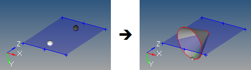
Figure 4. . This example uses a top radius of 0.5, base radius of 3, and height of 4.
| Option | Action |
|---|---|
| bottom center | Select the node that defines the center of the bottom cone face. |
| normal vector | Select the vector between the bottom center node and the normal vector node defines the cone axis, thereby indicating the cone orientation. This does not indicate the actual cone height. |
| Top radius | Specify the top radius of the top cone face. If set to 0, a cone tip is created; if greater than zero, the cone has a flat top. |
| Base radius | Specify the base radius of the bottom cone face. This value must be greater than 0. |
| Height | Specify the cone height. |
 Cone Partial Subpanel

Figure 5. . This example uses a top radius of 0.5, base radius of 3, height of 4, start angle 45, end angle 320, and axis ratio 1.0.
| Option | Action |
|---|---|
| bottom center | Select the node that defines the center of the bottom cone face. |
| normal vector | Select the vector between the bottom center node and the normal vector node that defines the cone axis, thereby indicating the cone orientation. This does not indicate the actual cone height. |
| major vector | Select the vector between the bottom center node and the major vector node that determines the zero-degree point of an arc defining the curved surface of the partial cone. This arc extends in a direction based on the normal vector using the right-hand rule, with its start angle and end angle specified relative to this vector. |
| Top radius | Specify the radius of the top cone face. If set to 0, a cone tip is created; if greater than zero, the cone has a flat top. |
| Base radius | Specify the radius of the bottom cone face. Must be greater than 0. |
| Height | Specify the distance between the cone's base and its top. |
| Start angle | Specify the starting arc angle, measured from the major vector node in a direction based on the normal vector using the right-hand rule. |
| End angle | Specify the ending arc angle, measured from the major vector node in a direction based on the normal vector using the right-hand rule. The difference between this and the start angle determines the arc of the partial cone, and therefore the arc of the cutout in the partial cone. For example, if your start angle is 15 degrees, and your end angle is 285 degrees, the resulting cone has a base with a 270 degree arc and a 90 degree cut. |
| Axis ratio | Specify the percentage of the major vector. This value must
be greater than zero and less than or equal to 1. Decimal values
create oval-shaped cones instead of circular ones.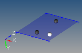 Figure 6. . This example uses the same settings as the previous one, but with axis ratio 0.5 |
 Sphere Center and Radius Subpanel
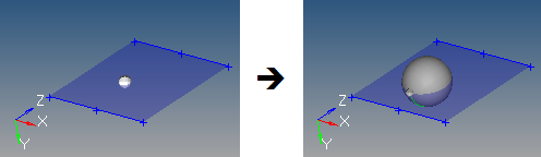
Figure 7.
| Option | Action |
|---|---|
| center | Select the node that defines the center of the sphere. |
| Radius | Define the sphere radius. A value can be specified, or a node that defines the radius (measured from the center node) can be selected. |
 Sphere Four Nodes Subpanel
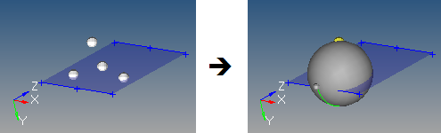
Figure 8.
| Option | Action |
|---|---|
| node list | Select nodes. The selected nodes cannot all be coplanar. The smallest sphere that passes through all four nodes is created. If more than four nodes are selected, only the four most recent are used. |
 Sphere Partial Subpanel
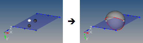
Figure 9. . This example uses theta begin 45, theta end 270, phi begin -90, and phi end 90.
| Option | Action |
|---|---|
| center | Select the node that defines the center of the sphere. |
| R node | Select the vector between the center node and R node that defines the first axis of the sphere. |
| phi/theta | Select the node (phi or theta) that defines the second axis
and complete the definition of the sphere's orientation.
|
| Radius | Specify the sphere radius. |
| Theta begin | Specify the starting angle for theta. Valid values for theta are from 0.0 to 360.0. |
| Theta end | Specify the ending angle for theta. |
| Phi begin | Specify the starting angle for phi. Valid values for phi are from 0.0 to 90.0. |
| Phi end | Specify the ending angle for phi.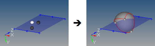 Figure 10. . This example uses theta begin 45, theta end 270, phi begin -30, and phi end 90. |
 Torus Center and Radius Subpanel
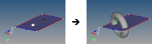
Figure 11. . The highlighted node is the center; the dark one is the normal; this torus has a major radius of 3 and minor radius of 1.
| Option | Action |
|---|---|
| center | Select the node that defines the center of the torus. |
| normal vector | Select the vector between the center node and the normal vector node that is the torus axis, thereby defining the torus orientation. |
| Major radius | Specify the outside radius of the torus, measured from the center node. |
| Minor radius | Specify the radius of the circular cross-section of the torus. |
 Torus Three Nodes Subpanel
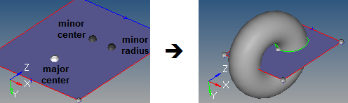
Figure 12. . The nodes define the torus major and minor radii as well as its orientation.
| Option | Action |
|---|---|
| major center | Select the node that defines the absolute center of the torus. |
| minor center | Select the node that defines the center of the circular cross-section of the torus. |
| minor radius | Distance between the minor center node and the minor radius node defines the radius of the circular cross-section of the torus. |
 Torus Partial Subpanel
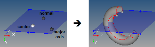
Figure 13. . In this example, the major radius is 3 and major start/end angles are 30 and 270, while the minor radius is 1 and the minor start/end angles are -120 and 120.
| Option | Action |
|---|---|
| center | Select the node that defines the absolute center of the torus. |
| normal | Select the vector between the center node and the normal node that defines the torus axis. |
| major axis | Select the vector from the center node to the major axis node which completes the definition of the torus plane. Combined with the normal node, this provides the complete torus orientation. |
| Major radius | Specify the outside radius of the torus, measured from the center node. |
| Major start angle | Specify the starting arc angle for the major circumference (ring), measured from the torus plane in a direction based on the torus axis using the right-hand rule. |
| Major end angle | Specify the ending arc angle for the major circumference (ring), measured from the torus plane in a direction based on the torus axis using the right-hand rule. The difference between this and the major start angle determines the major arc of the torus, and therefore the arc of the major cutout in the partial torus. For example, if your major start angle is 15 degrees, and your major end angle is 285 degrees, the resulting torus is an open ring with a 270 degree arc and a 90 degree cut. |
| Minor radius | Specify the radius of the circular cross-section of the torus. |
| Minor start angle | Specify the starting arc angle for the minor circumference (cross-section), measured from the mid-plane of the cross-section in a direction based on the cross-section centerline using the right-hand rule. |
| Minor end angle | Specify the ending arc angle for the minor circumference (cross-section), measured from the mid-plane of the cross-section in a direction based on the cross-section centerline using the right-hand rule. The difference between this and the minor start angle determines the minor arc of the torus, and therefore the arc of the minor cutout in the partial torus. For example, if your minor start angle is 15 degrees, and your minor end angle is 285 degrees, the resulting torus has a cross-section with a 270 degree arc and a 90 degree cut. |
 Spin Subpanel
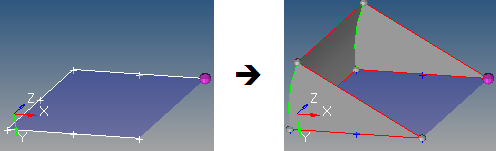
Figure 14.
| Option | Action |
|---|---|
| lines/node list selector | Select the lines or node list to spin. If a node list is specified, a line will first be fit through the specified nodes. |
| plane and vector selector | Select the plane/vector that defines the rotation axis. If a vector is defined or selected, this represents the axis of rotation. If a plane is defined, the plane normal represents the axis of rotation. The base node of the plane/vector represents the center of rotation. |
| Merge input lines | Merge the input lines into smooth lines when possible, and
create a surface for each group that forms a tangentially
continuous line. Clear this checkbox to create a surface for each input line, with shared edges connecting surfaces where relevant. 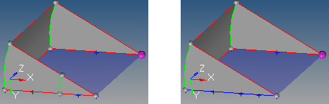 Figure 15. . The results on the left preserve the two input lines in the foreground; the image on the right merges them. Note: Available when the entity selector is set to
lines.
|
| Create in | Choose where to organize the resulting surface component.
Note: Available when the entity selector is set to
lines.
|
| Start angle | Specify the start angle that defines the initial angle before the lines/nodes are spun. The angle is measured about the axis of rotation using the right-hand rule. |
| End angle | Specify the end angle that defines the final angle through which the lines/nodes are spun. The angle is measured about the axis of rotation using the right-hand rule. The total angle is given by (end angle - start angle). |
| spin+ / spin- | Define the direction of the spin.
|
 Drag Along Vector Subpanel
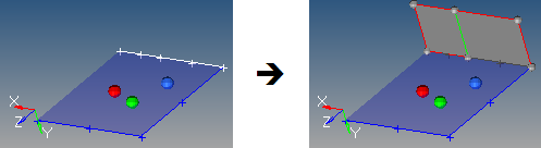
Figure 16. . The three nodes on the plane define the vector (via the right=hand rule) to drag the selected lines along.
| Option | Action |
|---|---|
| lines/node list selector | Select the lines or node list to drag. If a node list is specified, a line will first be fit through the specified nodes. |
| plane and vector selector | Select the plane/vector defining the drag direction. If a vector is defined or selected, this represents the positive drag direction. If a plane is defined, the plane normal represents the positive drag direction. |
| Merge input lines | Merge the input lines into smooth lines when possible, and
create a surface for each group that forms a tangentially
continuous line.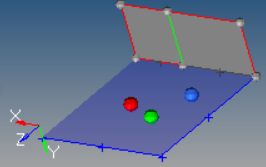 Figure 17. Merged Lines Clear this checkbox to create a surface for each input
line, with shared edges connecting surfaces where
relevant.
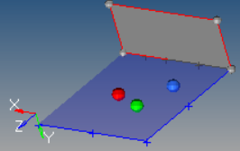 Figure 18. Unmerged Lines Note: Available when the entity selector is set to
lines.
|
| Create in | Choose where to organize the resulting surface component.
Note: Available when the entity selector is set to
lines.
|
| Distance | Specify the length to drag the lines/nodes along the vector. |
| spin+ / spin- | Define the direction of the drag.
|
 Drag Along Line Subpanel
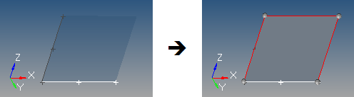
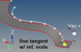
Figure 19. . In this example, the white line is dragged along the dark gray line list one to produce a new surface.
- S
- Start of drag line (path), which is the closest end of the drag line to the vertices of the line to be dragged. Drag + follows this direction. Drag - follows the opposite direction.
- T
- Tangent of the drag line at S.
- R
- Reference node.
- B
- Base node of the transformation plane.
- N
- Normal vector of the transformation plane.
| Option | Action | ||
|---|---|---|---|
| lines / node list | Select the lines or node list to drag. If a node list is specified, a line will first be fit
through the specified nodes and then dragged.
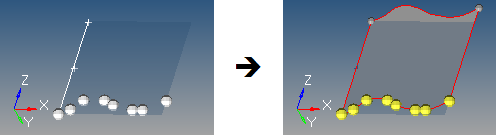 Figure 20. |
||
| line list | Select the lines that the drag will follow. This can also be a series of connected lines. | ||
| Merge input lines | Merge the input lines into smooth lines when possible, and
create a surface for each group that forms a tangentially
continuous line. Clear this checkbox to create a surface for each input line, with shared edges connecting surfaces where relevant. Note: Available when the entity selector is set
to lines.
|
||
| Create in | Choose where to organize the resulting surface component.
Note: Available when the entity selector is set to
lines.
|
||
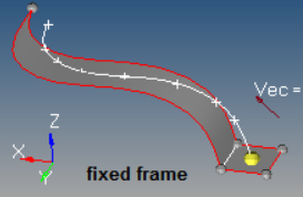
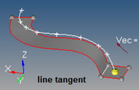
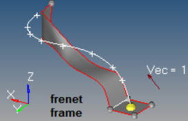
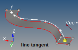
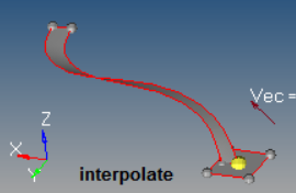
| Frame mode | Choose a method for how lines are translated and rotated
during the drag. In some cases, the differences are only
apparent when performing relatively complex drags.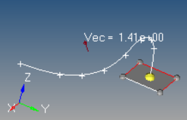 Figure 21. . The highlighted line of the rectangular surface is dragged along the curved line, which curves in 3 dimensions.
|
||
| Reference node | Select the node used to translate the drag (path) line prior
to the drag, thus producing results as if the drag line actually
began at the selected reference node. By default, R=S. If a
different S is specified, the line list is translated by the
vector defined from S to R.
|
||
| Transformation | Select the plane used to translate and rotate the input lines
prior to the drag. By default, no transformation occurs (B=R and
N=T). If specified, the lines are translated by the vector
defined from R to B, and are rotated from N to T. Figure 26. Transformation Plane Example. R is white, and B is purple. |
||
| drag+ / drag- | Define the direction of the drag.
|
 Drag Along Normal Subpanel
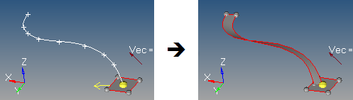
Figure 27. Drag Along Normal Example. The yellow arrow indicates the starting normal direction for the selected (white) line.
| Option | Action | ||
|---|---|---|---|
| line list | Select the line list to drag. | ||
| Create in | Choose where to organize the resulting surface component.
Note: Available when the entity selector is set to
lines.
|
||
| Distance | Choose a method for defining the length to drag the line
along its normal.
|
||
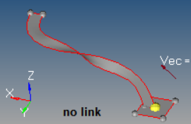
| Link type | Choose a method used to determine how the surface is
generated when there is a discontinuity (other than 180 degrees)
in the direction of the curvature of the input line list.
|
||
| Switch start point | By default, the start of the line is indicated by the end of the chain that has the arrow after selecting the lines. Enable this checkbox to reverse the start point. | ||
| drag+ / drag- | Define the direction of the drag.
|
 Drag Along Normal from Surface
Subpanel
Drag Along Normal from Surface
Subpanel
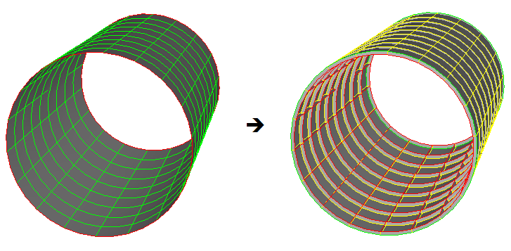
Figure 30.
| Option | Action |
|---|---|
| lines | Select the lines to drag. Note: Only surface edges may be
selected.
|
| Create in | Choose where to organize the resulting surface component.
Note: Available when the entity selector is set to
lines.
|
| Distance | Specify the length to drag the line along its adjacent surface normal. Both positive and negative values are accepted. A negative value indicates to use the direction opposite the normal directions. |
| drag+ / drag- | Define the length to drag the line along its adjacent surface
normal. Both positive and negative values are accepted. A
negative value indicates to use the direction opposite the
normal directions.
|
 Ruled Subpanel
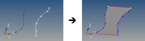
Figure 31.
| Option | Action |
|---|---|
| line list / node list | Use the first selector to define the first edge of the surface to
create. Use the second selector to define the second edge of the
surface to create. If a node list is selected, a line will first be fit through the specified nodes. |
| auto reverse | Prevent "bow tie" surfaces from being generated. The lines used to create the surface can be ordered in different directions. This results in a surface that crosses itself resembling a bow tie. Enabling this option ensures that surfaces are generated with a similar order on each side. |
 Spline/Filler Subpanel
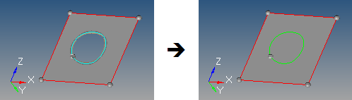
Figure 32.
| Option | Action |
|---|---|
| entity selector | Select the lines, node list, or points that define the
spline/filler area.
|
| Auto create (free edges only) | Create the surface as soon as a closed-loop free surface edge
is selected. This provides a single-click ability to close holes
in an existing surface. When this option is enabled, surfaces
are created in the component of the selected surface edge, and
the topology is updated accordingly. Clear this checkbox to create the surface by selecting multiple bounding lines/edges. Note: Valid for free surface edge line
selection only.
|
| Keep tangency | Examine surfaces attached to the selected edges, and attempt
to create a surface tangent to them. This helps to form a smooth
transition to the surrounding surfaces. Note: Valid for surface
edge line selection only.
|
| Keep line endpoints for planar splines | Keep line endpoints of surfaces created with closed spline/filler lines. |
| Create in | Choose where to organize the resulting surface component.
Note: Available when the entity selector is set to
lines.
|
 Skin Subpanel
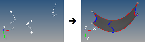
Figure 33.
| Option | Action |
|---|---|
| line list | Select the lines to use as input. The lines used to create the skin surface are automatically smoothed before the surface is created. As a result, the surface is created with a single face. |
| Auto reverse | Prevent "bow tie" surfaces from being generated. The lines used to create the surface can be ordered in different directions. This results in a surface that crosses itself resembling a bow tie. Enabling this option ensures that surfaces are generated with a similar order on each side. |
 Fillet Subpanel
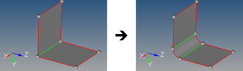
Figure 34.
If an edge (or edge chain) is curved, HyperWorks can only fillet with a radius that is smaller than the radius of the edge curve, in order to avoid the fillet intersecting itself.
In addition, care must be taken such that different fillets do not overlap (for example, if two unrelated parallel edges are filleted, the fillet radius must be small enough so that the two fillets do not interfere with each other).
There are known issues in which sometimes fillets are too short, or do not complete the trim of the surfaces being filleted. Sometimes this leads to a false decision of what should be deleted and what should be kept, and a useful surface is deleted. Many times, changing the cleanup tol in the Options panel fixes this. If it cannot be fixed this way, a workaround is to complete the trim manually using other functions; if needed, uncheck delete trimmed surface chips, create the fillet, complete the trim using manual methods, then delete what is not needed and organize the other surfaces as required.
| Option | Action |
|---|---|
| lines | Select the lines that define the surface edges to use as input. |
| Auto select whole edge | Select additional surface edges connected to the original
selection, based on the pick angle and x stop control
settings.
|
| Edit Fillet Options | Access additional fillet options.
|
| Radius | Specify the radius of the fillet to create. |
 From FE Subpanel
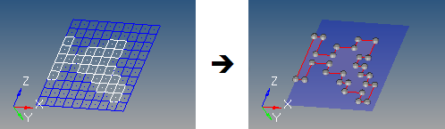
Figure 35. . In this example the mesh is changed from wireframe to transparent to make the surface more visible.
| Option | Action |
|---|---|
| elems | Select the shell elements used to generate surfaces. In order to create surfaces from solid elements, create faces using the Faces panel and select the elements in the ^faces component. |
| Auto Detect Features / feature edges | Choose a method for selecting features (surface edges).
|
| Mesh-Based Auto Tol / Tolerance | Choose a method to determine how closely the new surfaces
adhere to the underlying elements. The tolerance value is the
maximum distance by which the surface created differs from the
selected elements at any location. This is particularly
important for curved meshes.
|
| Surface Complexity | Affects how many surfaces are created. This option takes into
account a number of factors, including the boundary shape of the
area to be surfaces as well as its topology. Higher complexity
values create a smaller number of more complex surfaces, but
require longer calculation times to create those surfaces.
Smaller values produce a larger number of smaller, simpler
surfaces, but do so more rapidly.
|
| Split by components | Maintain boundaries between adjacent components, so that a single mesh plane will still produce separate surfaces based on the components that the elements belong to. |
| Associate nodes | Ensure that the mesh nodes are associated to the new corresponding surfaces. This allows re-meshing of the surface to replace the original mesh instead of creating a new overlaid mesh. |
 Meshlines Subpanel
Use the Meshlines subpanel to create a mesh line, which is a line on the elements of a 2D (shell) mesh that is associated with the mesh by retaining information about where it enters and exits each shell element.
For a closed chain of mesh lines, you can select the elements or nodes inside the chain and save them as collections for retrieval in other panels. This can be useful for application of loads, selection of a region to morph, or construction of CAD surfaces close to the mesh using the mesh line chain approximations as the surface borders.
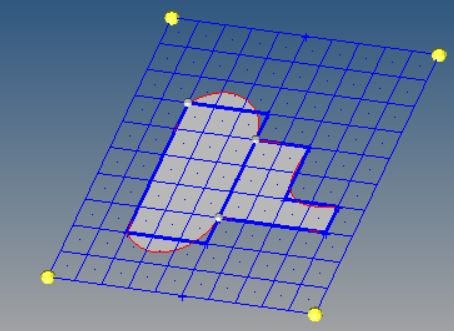
Figure 36. . The mesh lines are blue, the surfaces are gray, and the splined surface edges are red.
| Option | Action |
|---|---|
| Collections | While not related to generating mesh lines, the collections option enable you to use existing closed mesh line chains as boundaries to quickly and easily select groups of nodes or elements that may form an irregular shape. Click Collections to select a node or element; if the selection resides inside a closed chain of mesh lines, then all of the nodes/elems within the chain will be selected automatically. Once this selection is made, you can click the selector and click save from the extended entity selection menu. Once saved, this collection of nodes or elements can be retrieved from the extended entity selection menu on other panels, such as load-related panels (forces, pressures, fluxes, and so on. ) |