Constraints Panel
Use the Constraints panel to place constraints or enforced displacements on a model. This is accomplished by assigning a degree of freedom (DOF) constraint to the node.
Location: Analysis page
Constraints are load config 3 and are displayed with a triangle that connects to the node, with the dof numbers that apply to the node beside the triangle.
While both subpanels share many common inputs, the settings you specify are not shared between them, for example, you can change the value for each degree of freedom on the Edit subpanel without changing the values already specified for the same DOF's on the Create subpanel.
Create Subpanel
| Option | Action |
|---|---|
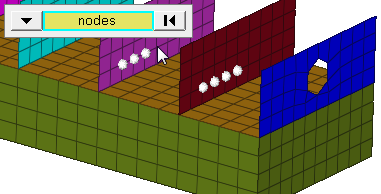
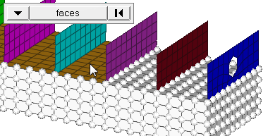
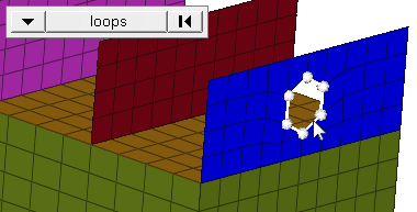
| entity selector | Select entities. In any case, the constraints are applied to nodes; this selection simply determines how those nodes are selected. Geometric points select the nodes at which they exist. Comps select all of the nodes contained within the chosen component. If you choose comps or sets, the constraints are drawn using a single indicator. When
nodes is selected, click the switch to change the selection mode.
|
| display |
Indicate where in the model to draw the indicator.
Important: Only available when the entity selector is set to comps or
sets.
|
| relative size | Specify the size, in model units, to display constraints relative to the model size. |
| label constraints | Show text labels next to constraints in the modeling window. |
| constant value / curve | Select whether the constraint should be a constant value or use curve-based values. If curve, choose the desired curve. |
| fixed | Select whether the constraint should be fixed. |
| face angle / individual selection |
|
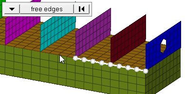
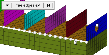
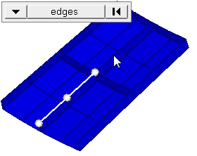
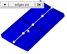
| edge angle |
Split edges that belong to a given face. When the edge
angle is 180 degrees, edges are the continuous boundaries of faces. For smaller
values, these same boundary edges are split wherever the angle between segments
exceeds the specified value. A segment is the edge of a single element.
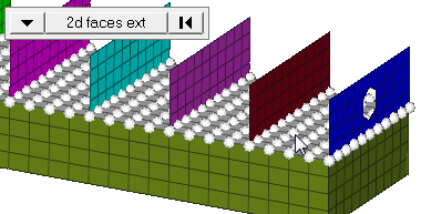
Important: Only available when the entity selector is set to nodes and the
selection mode is set to free edges, free edges ext, edges, or edges
ext.
|
| xscale | Change the value to alter the curve’s X scale (for example, time). |
| dof1 - dof6 | Select the degree of freedom that you wish to constrain, then enter a value for the constraint. |
| load types | Select a load
type. The available types depend on the current solver interface selected. |
Update Subpanel
| Input | Action |
|---|---|
| entity selector | Select entities. In any case, the constraints are applied to nodes; this selection simply determines how those nodes are selected. Geometric points select the nodes at which they exist. Comps select all of the nodes contained within the chosen component. If you choose comps or sets, the constraints are drawn using a single indicator. When
nodes is selected, click the switch to change the selection mode.
|
| display |
Indicate where in the model to draw the indicator.
Important: Only available when the entity selector is set to comps or
sets.
|
| relative size | Specify the size, in model units, to display constraints relative to the model size. |
| label constraints | Show text labels next to constraints in the modeling window. |
| constant value / curve | Select whether the
constraint should be a constant value or use curve-based
values. If curve, choose the desired curve. |
| xscale | Change the value to alter the curve’s X scale (for example, time). |
| dof1 - dof6 | Select the degree of freedom that you wish to constrain, then enter a value for the constraint. |
| load types | Select a load
type. The available types depend on the current solver interface selected. |