Line Drag Panel
Use the Line Drag panel to create a two- or three-dimensional surface and/or mesh or elements by dragging nodes, lines, or elements along another line.
Location: 2D and 3D pages
An example of using the Line Drag panel is illustrated in the design of an exhaust pipe. You can create a cross section of the pipe and drag it along the curved line which represents the pipe. Another example of its use is in the design of a window frame. A cross section of the molding can be created and dragged along the complex curves of the frame.
Drag Geoms Subpanel
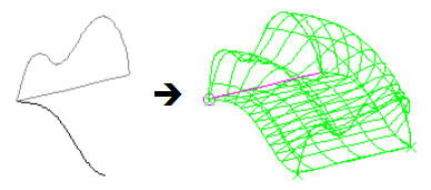
Figure 1.
The orientation vector is used to orient the line being dragged to the tangent of the guide line. If the orientation vector is not initially pointing in the same direction as the tangent of the guide line, the section will be oriented. This may result in the section being rotated. To prevent the section from being rotated, select the orientation vector so that it is along the tangent of the guide line.
Line segments can be used on both of the lines by selecting points on the line.
Surfaces can only be created by dragging a planar line along a guide line. If the line being dragged is not planar, it is projected to the appropriate plane. The mesh w/o surf option does not have this limitation, and does not project the line being dragged to a plane. If line drag, with mesh w/o surf selected, is used before entering the automeshing module, the placement of the displayed nodes for the "along" edges gives only an approximation of where they are actually created when the mesh is generated. Indeed, the lines themselves are only approximations; if the drag is very complex, they may degenerate into a straight line. This does not affect the actual mesh.
| Option | Action |
|---|---|
| drag: node list / line list | Select the nodes or
lines that you wish to drag.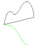 Figure 2. Two Lines Selected |
| along: line list | Select the guide line along which you want to drag the
entities.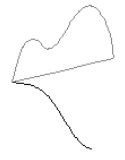 Figure 3. |
| use default vector / specify vector |
Choose the direction for the drag.
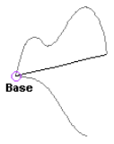 Figure 4. |
| (Mesh options switch) | Select the desired mesh and surface option. |
Drag Elems Subpanel
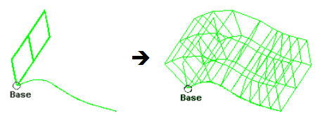
Figure 5.
| Option | Action |
|---|---|
| drag: elems | Select the elements to
drag.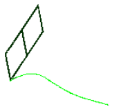 Figure 6. |
| along: line list | Select the guide line along which you want to drag the
entities.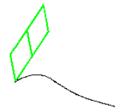 Figure 7. |
| use default vector / specify vector |
Choose the direction for the drag.
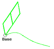 Figure 8. |
| on drag = | Specify the number of two-dimensional elements to be created along the guide line. |
| bias style | Choose between linear, exponential, or bellcurve bias. This affects the spacing of the 2D elements created during the drag. |
| bias intensity = | Specify the strength of the biasing effect. A value of zero indicates no biasing at all. |
Command Buttons
| Button | Action |
|---|---|
| drag | Perform the drag. |
| reject | Undo the most recent drag, deleting all geometry or elements created by the drag operation. |
| return | Exit the panel. |