Planar Results (Volumetric)
The purpose of this tool is to calculate and derive the normal stress and shear stress for imaginary planes such as a fracture (joint) set within a 3D volume.
-
Select the Planar Results
(volumetric) tool from the Select GeoD Tool dropdown list.
 Figure 1.
 -
Click on the file browser button
 adjacent to the Load Model field and browse and select the
demo-eff-geo.h3d file and click Open.
adjacent to the Load Model field and browse and select the
demo-eff-geo.h3d file and click Open.
-
Click Apply.
The model and result files are loaded in the HyperView window.
 Figure 2.
 -
Select the FindElastoplasticEquilibrium subcase checkbox from the
Subcase table.
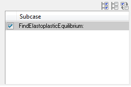 Figure 3. Note: Once you select the subcase, all the other sections is activated.
Simulation
-
Select the required simulation from the Simulation table.
 Figure 4.
Derived Results
-
By default, the S-Global-Stress components
IP-Effective Geo is selected in the Derived Results table.
 Figure 5. Note: You can select any one stress type or all of the stresses for deriving additional results.
 -
Select the required results from the Results to Propagate table to propagate into the new h3d file.
 Figure 6. Note: You can propagate the results from ODB file to H3D file by selecting the results from the Results to Propagate table. Uncheck the results that are not required to be propagated into the new h3d file.
Components
-
Click the Components button.
Extended Entity Selection window opens.
 Figure 7.
 -
Click the Displayed button adjacent to the Components button.
 Figure 8. The components is highlighted in the graphics area.
 -
Enter the values in the Dip
(deg) and Dip Direction
(deg) fields and press enter.
The normal the planes are calculated and displayed in the Normal to Plane field.
 Figure 9.
 -
After defining the required inputs, click the file browser button in
the Output file text field.
A file selection window opens.
-
Click Generate H3D.
An information message is displayed.
 Figure 10.
 -
Once the H3D file is generated, a confirmation window opens.
 Figure 11.