Setup

Create and assign various solver deck parameters.

Using the Setup group of tools, you will define following parameters -
  1. Materials
  2. Properties
  3. Sets
  4. Loads
  5. Boundary Conditions
  6. Load Steps, and
  7. Output Blocks

Materials

Create and assign materials to volumes.

You will create and assign materials to all the volumes in the model. Below are the list of materials and their respective material properties that you will create in SI units (pa;kg/m3):
Name Young’s Modulus Density Poisson’s Ratio
Rock01 3e+09 1800 0.18
Rock02 7.5e+09 2200 0.25
Rock03 9.25e+09 2325 0.28
Rock04 15e+09 2450 0.30
Rock05 17.25e+09 2250 0.30
Rock06 25.0e+09 2800 0.35
  1. From Define group, select Materials.
    Figure 1.
    GeoD - Material dialog will appear.
  2. Enter Rock01 in Material value field.
  3. Define the material property values as listed in the above table and click Create.
  4. Repeat above steps to create all the materials listed in the table.
Material creation also creates respective Property(s) in the session.

Assign Materials

Assign materials to the volumes.

You will assign materials created in previous task to the volumes.
  1. From Setup ribbon, select Assign Materials tool.
    Figure 2.
    Material assignment guide bar will activate.
  2. Select a material for Material selection and a volume component for Component selection and click Assign.
  3. Assign the materials to volume components as illustrated below.
    Figure 3.

Sets

Create Auto Node Sets and manual element sets.

You will create node and element sets which will be utilized for boundary and dynamic load definition.

Auto Node Sets

  1. From Setup ribbon, select Auto Sets tool.
    Figure 4.
    A Create Automatic Face Node Sets user message appears.
    Figure 5.
  2. Click Yes to auto create node sets.
    This will create all the required node sets and list in the model browser.
    Figure 6.

Element Sets

  1. From Setup ribbon, select Sets tool.
    Figure 7.
    A Create Sets for set creation appears.
    Figure 8.
  2. From Entity IDs option, select Elements.
  3. Enter TetraElementSet in Name value field.
  4. Select all the tetra elements from the graphic area.
    Gravity DLOAD will be applied on this element set.

Boundary Conditions

Create and assign boundary conditions.

You will create & assign boundary conditions utilizing the node and element sets created in the previous task. You will define a gravity box, the lateral extents of which cannot expand and with a base that doesn’t subside. To do this, we constrain the normal motion of each of the lateral extents as well as the base (the top is completely free to move in response to gravity) to be 0. In Abaqus, these are nodal constraints in one specific degree of freedom (DOF).
  1. From Setup ribbon, select Boundary Conditions (BCs) tools.
    Figure 9.
  2. GeoD - Boundary creation window will appear.
    Figure 10.
  3. Define the boundary constraints as listed below-
    NSET 1st DOF Last DOF
    NSet_NegativeX 1 1
    NSet_NegativeY 2 2
    NSet_NegativeZ 3 3
    NSet_PositiveX 1 1
    NSet_PositiveY 2 2
  4. Click Create Boundary.
    This creates boundary constraints on the node set.
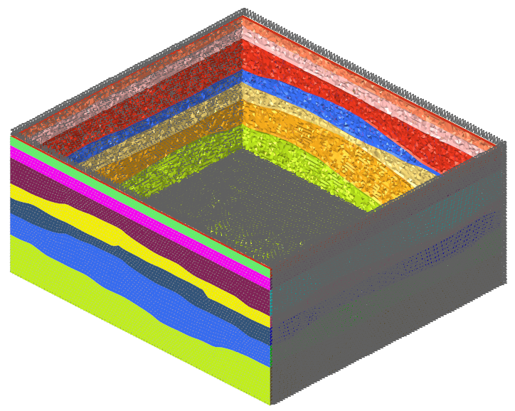
    Figure 11.

Loads

Define loads conditions for the model.

The body force is now applied to all the elements using the GRAV option of Abaqus’ DLOAD capability.
  1. From Setup ribbon, select Loads tools.
    Figure 12.
  2. GeoD - DLOAD creation window will appear.
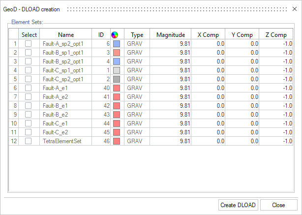
    Figure 13.
  3. Check the TetraElementSet box.
  4. Accept the default values for the Magnitude, X Comp, Y Comp and Z Comp and click Create DLOAD.
    This creates gravity load on the solid (that is, mass containing) elements in the model with magnitude 9.81 m/s2 in the downwards (-Z) direction.

Load Steps

Define a load step and simulation parameters.

You will create and define the simulation parameters based on the boundary and dynamic load collectors.
  1. From Setup ribbon, select Load Step tool.
    Figure 14.
    Create Loadsteps window will appear.
    Figure 15.
  2. Enter Gravity_Loading in Name field.
  3. Click Loadcol IDs.
    Load collectors window will appear.
  4. Select all the boundary and DLOAD collectors created in previous task.
  5. Accept the default values for all the parameters and click Close.
    This creates the loadstep and all the simulation parameters for the solver deck are assigned to it.
    This also auto creates an Output Block requesting the required simulation outputs for post processing.